III
- 12
[ 4 ]
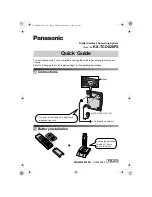
Copying mode (Solenoid: ON, Motor rotation: Forward)
In the copying mode, the control electronics activates the solenoid to release the stopper of arm A
from the clutch lever. When the motor rotates in the forward direction, sun gear 24/90 ("B") rotates
counterclockwise so that planet gear 34A ("J") transmits the torque to the document scanner
mechanism (e.g., the separation roller gear ("G"), LF roller gear ("I") and document ejection roller
gear ("H")) and planet gear 34B ("C") transmits the torque to the recording mechanism (e.g., platen
gear ("Y") and paper ejection roller gear ("R")).
If gear 39/62 ("V") rotates, gear 20 ("z") on the inner side of the drive unit also rotates so as to drive
the friction torque transmission ASSY and ribbon drive gear ("w") that rotates ribbon take-up gear
("a") on the ribbon cartridge, as shown on the next page.
Arm A Released from Cutout
of Clutch Lever
Active Gears on the Outer Side of the Drive Unit and on the Left Sides of the Platen Frame,
Main Frame and Control Panel ASSY
Summary of Contents for FAX 750
Page 4: ...CHAPTER I GENERAL DESCRIPTION ...
Page 11: ...CHAPTER II INSTALLATION ...
Page 12: ...CHAPTER III THEORY OF OPERATION ...
Page 14: ...III 1 1 OVERVIEW Not provided on the FAX 910 ...
Page 24: ...III 11 Active Gears on the Inner Side of the Drive Unit ...
Page 26: ...III 13 Active Gears on the Inner Side of the Drive Unit ...
Page 30: ...III 17 Location of Sensors and Actuators 1 ...
Page 31: ...III 18 Not provided on the FAX 910 Location of Sensors and Actuators 2 ...
Page 34: ...III 21 FAX750 FAX770 FAX 910 FAX 920 FAX 921 MFC 925 FAX870MC FAX 930 FAX 931 MFC970MC ...
Page 39: ...CHAPTER IV DISASSEMBLY REASSEMBLY LUBRICATION AND ADJUSTMENT ...
Page 44: ...IV 4 n n Disassembly Order Flow ...
Page 48: ...IV 8 4 Disconnect the panel main harness ...
Page 52: ...IV 12 ...
Page 70: ...IV 30 Remove the two screws and lift up the paper feed chute ...
Page 72: ...IV 32 ...
Page 78: ...IV 38 ...
Page 86: ...IV 46 1 17 Harness Routing ...
Page 88: ...IV 48 ...
Page 89: ...IV 49 2 LF roller ASSY 3 Platen frame ASSY ...
Page 90: ...IV 50 ...
Page 91: ...IV 51 4 Separation roller and main frame ...
Page 92: ...CHAPTER V MAINTENANCE MODE ...
Page 99: ...V 6 Scanning Compensation Data List ...
Page 150: ...CHAPTER VI ERROR INDICATION AND TROUBLESHOOTING ...
Page 168: ...July 98 5X4401 Printed in Japan ...
Page 177: ......
Page 178: ......
Page 182: ......
Page 184: ......
Page 197: ......
Page 198: ......
Page 202: ......
Page 216: ......
Page 218: ......