III
- 16
2.4
Sensors and Actuators
This equipment has five photosensors and two mechanical switches as described below.
Sensor name
Type
Located on
Document front sensor
Photosensor
Control panel PCB ASSY
Document rear sensor
Photosensor (PI2)
Main PCB
Paper-edge sensor
Photosensor (PH1)
Sensor PCB
Paper ejection sensor
Photosensor (PH2)
Sensor PCB
Ribbon sensor
Photosensor (PI1)
Main PCB
Cover sensor
Mechanical switch (SW1)
Main PCB
Hook switch sensor*
Mechanical switch (SW1)
Hook switch PCB
•
Document front sensor which detects the presence of documents.
•
Document rear sensor which detects the leading and trailing edges of pages to tell the control
circuitry when the leading edge of a new page has reached the starting position and when the
scan for that page is over.
•
Paper-edge sensor which detects the leading and trailing edges of paper and the presence of
paper as well as detecting whether the paper front cover is closed.
•
Paper ejection sensor which detects whether a paper jam has occurred.
•
Ribbon sensor which detects whether the ink ribbon is loaded.
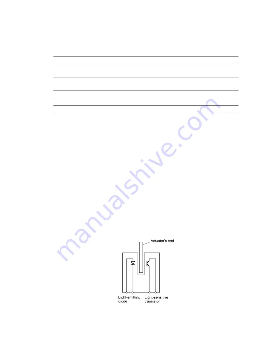
These photosensors are a photointerrupter consisting of a light-emitting diode and a light-sensitive
transistor. Each of them has an actuator separately arranged (see the following pages) except that
the paper-edge sensor has two actuators for sensing the paper and the paper front cover. When
an actuator is not activated, its black end lies in the path of light issued from the light-emitting diode
and interrupts its light so that the emitted light does not enter the light-sensitive transistor. If a
document, paper, or ribbon comes in so as to activate the actuator, the actuator's black end goes
out of the light path and the emitted light enters the light-sensitive transistor. This way, the sensor
detects the presence of documents, paper, or ink ribbon.
•
Cover sensor which detects whether the recording paper cover ASSY is closed.
•
Hook switch sensor* which detects whether the handset is placed on the handset mount.
The cover sensor has an actuator ASSY (consisting of two actuators and a spring). If you open the
recording paper cover ASSY, the actuator ASSY pops up to release the sensor.
*
Not provided on the FAX-910.
Summary of Contents for FAX 750
Page 4: ...CHAPTER I GENERAL DESCRIPTION ...
Page 11: ...CHAPTER II INSTALLATION ...
Page 12: ...CHAPTER III THEORY OF OPERATION ...
Page 14: ...III 1 1 OVERVIEW Not provided on the FAX 910 ...
Page 24: ...III 11 Active Gears on the Inner Side of the Drive Unit ...
Page 26: ...III 13 Active Gears on the Inner Side of the Drive Unit ...
Page 30: ...III 17 Location of Sensors and Actuators 1 ...
Page 31: ...III 18 Not provided on the FAX 910 Location of Sensors and Actuators 2 ...
Page 34: ...III 21 FAX750 FAX770 FAX 910 FAX 920 FAX 921 MFC 925 FAX870MC FAX 930 FAX 931 MFC970MC ...
Page 39: ...CHAPTER IV DISASSEMBLY REASSEMBLY LUBRICATION AND ADJUSTMENT ...
Page 44: ...IV 4 n n Disassembly Order Flow ...
Page 48: ...IV 8 4 Disconnect the panel main harness ...
Page 52: ...IV 12 ...
Page 70: ...IV 30 Remove the two screws and lift up the paper feed chute ...
Page 72: ...IV 32 ...
Page 78: ...IV 38 ...
Page 86: ...IV 46 1 17 Harness Routing ...
Page 88: ...IV 48 ...
Page 89: ...IV 49 2 LF roller ASSY 3 Platen frame ASSY ...
Page 90: ...IV 50 ...
Page 91: ...IV 51 4 Separation roller and main frame ...
Page 92: ...CHAPTER V MAINTENANCE MODE ...
Page 99: ...V 6 Scanning Compensation Data List ...
Page 150: ...CHAPTER VI ERROR INDICATION AND TROUBLESHOOTING ...
Page 168: ...July 98 5X4401 Printed in Japan ...
Page 177: ......
Page 178: ......
Page 182: ......
Page 184: ......
Page 197: ......
Page 198: ......
Page 202: ......
Page 216: ......
Page 218: ......