IV
- 5
1.1
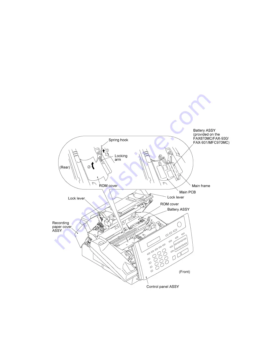
ROM Cover, Battery ASSY* and Ribbon Shaft Stopper
(*FAX870MC/FAX-930/FAX-931/MFC970MC)
(1) Open the control panel ASSY to the front.
(2) Pull up the lock levers and open the recording paper cover ASSY to the rear.
(3) As shown below, insert the tip of the spring hook at the center or right half of the locking arm
(when viewed from the front), then lift up the hook to release and move the ROM cover to the
right.
(4) FAX870MC/FAX-930/FAX-931/MFC970MC: To replace the battery ASSY (Ni-MH battery),
plug the power cord of the facsimile equipment into a wall socket, disconnect the battery
harness from the main PCB, and take out the battery ASSY from the main frame. Set a new
battery ASSY and unplug the power cord.
Disconnecting the battery harness with the power cord unplugged will lose the settings (e.g.,
calendar clock, voice messages, and received FAX data) stored in the RAM.
If you do not need to replace the battery ASSY, take out the battery ASSY from the main frame
and put it on the main PCB with the battery harness being connected.
Summary of Contents for FAX 750
Page 4: ...CHAPTER I GENERAL DESCRIPTION ...
Page 11: ...CHAPTER II INSTALLATION ...
Page 12: ...CHAPTER III THEORY OF OPERATION ...
Page 14: ...III 1 1 OVERVIEW Not provided on the FAX 910 ...
Page 24: ...III 11 Active Gears on the Inner Side of the Drive Unit ...
Page 26: ...III 13 Active Gears on the Inner Side of the Drive Unit ...
Page 30: ...III 17 Location of Sensors and Actuators 1 ...
Page 31: ...III 18 Not provided on the FAX 910 Location of Sensors and Actuators 2 ...
Page 34: ...III 21 FAX750 FAX770 FAX 910 FAX 920 FAX 921 MFC 925 FAX870MC FAX 930 FAX 931 MFC970MC ...
Page 39: ...CHAPTER IV DISASSEMBLY REASSEMBLY LUBRICATION AND ADJUSTMENT ...
Page 44: ...IV 4 n n Disassembly Order Flow ...
Page 48: ...IV 8 4 Disconnect the panel main harness ...
Page 52: ...IV 12 ...
Page 70: ...IV 30 Remove the two screws and lift up the paper feed chute ...
Page 72: ...IV 32 ...
Page 78: ...IV 38 ...
Page 86: ...IV 46 1 17 Harness Routing ...
Page 88: ...IV 48 ...
Page 89: ...IV 49 2 LF roller ASSY 3 Platen frame ASSY ...
Page 90: ...IV 50 ...
Page 91: ...IV 51 4 Separation roller and main frame ...
Page 92: ...CHAPTER V MAINTENANCE MODE ...
Page 99: ...V 6 Scanning Compensation Data List ...
Page 150: ...CHAPTER VI ERROR INDICATION AND TROUBLESHOOTING ...
Page 168: ...July 98 5X4401 Printed in Japan ...
Page 177: ......
Page 178: ......
Page 182: ......
Page 184: ......
Page 197: ......
Page 198: ......
Page 202: ......
Page 216: ......
Page 218: ......