IV
- 11
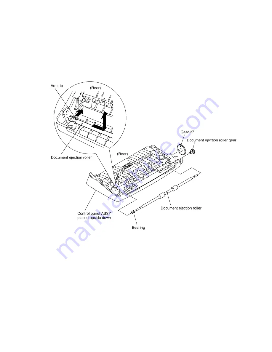
(5) To remove the document ejection roller, push the arm rib to the rear and shift the document
ejection roller to the right.
Pull out the document ejection roller gear and remove gear 37.
Pull out the document ejection roller to the left.
Remove the bearing.
(6) Remove the two screws from the panel rear cover. (See the next page.)
(7) Unhook the panel rear cover from the four "X" latches provided on the control panel and lift up
the panel rear cover.
(8) Remove the document front sensor actuator from the panel rear cover by turning it clockwise
(in the direction of arrow
•
) and moving it in the direction of arrow
‚
.
(9) Remove the screw from the document front sensor PCB.
(10) FAX750/FAX770/FAX-910/FAX-920/FAX-921/MFC-925: Unhook the control panel PCB from
the two "Y" latches.
FAX870MC/FAX-930/FAX-931/MFC970MC: Remove the screw from the control panel PCB
and unhook the PCB from the two "Y" latches. Disconnect the microphone.
Summary of Contents for FAX 750
Page 4: ...CHAPTER I GENERAL DESCRIPTION ...
Page 11: ...CHAPTER II INSTALLATION ...
Page 12: ...CHAPTER III THEORY OF OPERATION ...
Page 14: ...III 1 1 OVERVIEW Not provided on the FAX 910 ...
Page 24: ...III 11 Active Gears on the Inner Side of the Drive Unit ...
Page 26: ...III 13 Active Gears on the Inner Side of the Drive Unit ...
Page 30: ...III 17 Location of Sensors and Actuators 1 ...
Page 31: ...III 18 Not provided on the FAX 910 Location of Sensors and Actuators 2 ...
Page 34: ...III 21 FAX750 FAX770 FAX 910 FAX 920 FAX 921 MFC 925 FAX870MC FAX 930 FAX 931 MFC970MC ...
Page 39: ...CHAPTER IV DISASSEMBLY REASSEMBLY LUBRICATION AND ADJUSTMENT ...
Page 44: ...IV 4 n n Disassembly Order Flow ...
Page 48: ...IV 8 4 Disconnect the panel main harness ...
Page 52: ...IV 12 ...
Page 70: ...IV 30 Remove the two screws and lift up the paper feed chute ...
Page 72: ...IV 32 ...
Page 78: ...IV 38 ...
Page 86: ...IV 46 1 17 Harness Routing ...
Page 88: ...IV 48 ...
Page 89: ...IV 49 2 LF roller ASSY 3 Platen frame ASSY ...
Page 90: ...IV 50 ...
Page 91: ...IV 51 4 Separation roller and main frame ...
Page 92: ...CHAPTER V MAINTENANCE MODE ...
Page 99: ...V 6 Scanning Compensation Data List ...
Page 150: ...CHAPTER VI ERROR INDICATION AND TROUBLESHOOTING ...
Page 168: ...July 98 5X4401 Printed in Japan ...
Page 177: ......
Page 178: ......
Page 182: ......
Page 184: ......
Page 197: ......
Page 198: ......
Page 202: ......
Page 216: ......
Page 218: ......