


IV
- 13
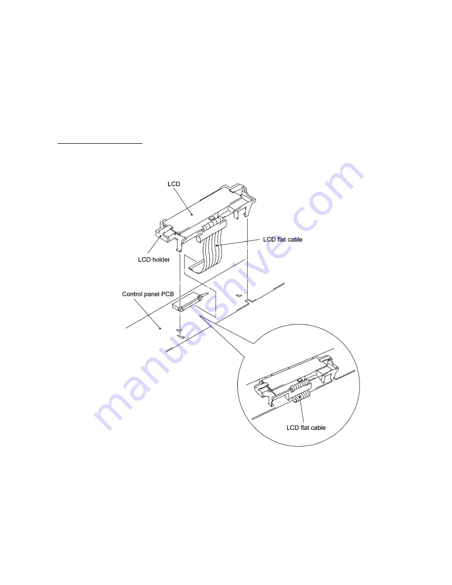
(11) To remove the LCD, unhook the four "Z" latches of the LCD holder from the control panel PCB.
Unlock the LCD cable connector and disconnect the LCD flat cable. Slide the LCD to the cable
side and remove it from the LCD holder.
NOTE:
Do not take out the LCD except when the LCD is defective and requires replacement.
(12) Unlock the FPC key connector and disconnect the FPC key.
n
n
Reassembling Notes
•
A new LCD is covered with a protection sheet. Before installing it, remove the protection sheet.
•
As shown below, route the LCD flat cable and set the LCD holder on the control panel PCB.
•
Before reinstalling the control panel PCB to the control panel, wipe fingerprints off the LCD
surface with a soft cloth.
•
After assembling the document pressure bar and its support together, check that the boss of the
document pressure bar is fitted in the hole provided in the support.
•
After reinstalling the assembly of the document pressure bar and its support to the control panel
ASSY, attach the white film, referring to the illustration given on page IV-10.
Summary of Contents for FAX 750
Page 4: ...CHAPTER I GENERAL DESCRIPTION ...
Page 11: ...CHAPTER II INSTALLATION ...
Page 12: ...CHAPTER III THEORY OF OPERATION ...
Page 14: ...III 1 1 OVERVIEW Not provided on the FAX 910 ...
Page 24: ...III 11 Active Gears on the Inner Side of the Drive Unit ...
Page 26: ...III 13 Active Gears on the Inner Side of the Drive Unit ...
Page 30: ...III 17 Location of Sensors and Actuators 1 ...
Page 31: ...III 18 Not provided on the FAX 910 Location of Sensors and Actuators 2 ...
Page 34: ...III 21 FAX750 FAX770 FAX 910 FAX 920 FAX 921 MFC 925 FAX870MC FAX 930 FAX 931 MFC970MC ...
Page 39: ...CHAPTER IV DISASSEMBLY REASSEMBLY LUBRICATION AND ADJUSTMENT ...
Page 44: ...IV 4 n n Disassembly Order Flow ...
Page 48: ...IV 8 4 Disconnect the panel main harness ...
Page 52: ...IV 12 ...
Page 70: ...IV 30 Remove the two screws and lift up the paper feed chute ...
Page 72: ...IV 32 ...
Page 78: ...IV 38 ...
Page 86: ...IV 46 1 17 Harness Routing ...
Page 88: ...IV 48 ...
Page 89: ...IV 49 2 LF roller ASSY 3 Platen frame ASSY ...
Page 90: ...IV 50 ...
Page 91: ...IV 51 4 Separation roller and main frame ...
Page 92: ...CHAPTER V MAINTENANCE MODE ...
Page 99: ...V 6 Scanning Compensation Data List ...
Page 150: ...CHAPTER VI ERROR INDICATION AND TROUBLESHOOTING ...
Page 168: ...July 98 5X4401 Printed in Japan ...
Page 177: ......
Page 178: ......
Page 182: ......
Page 184: ......
Page 197: ......
Page 198: ......
Page 202: ......
Page 216: ......
Page 218: ......


