


IV
- 33
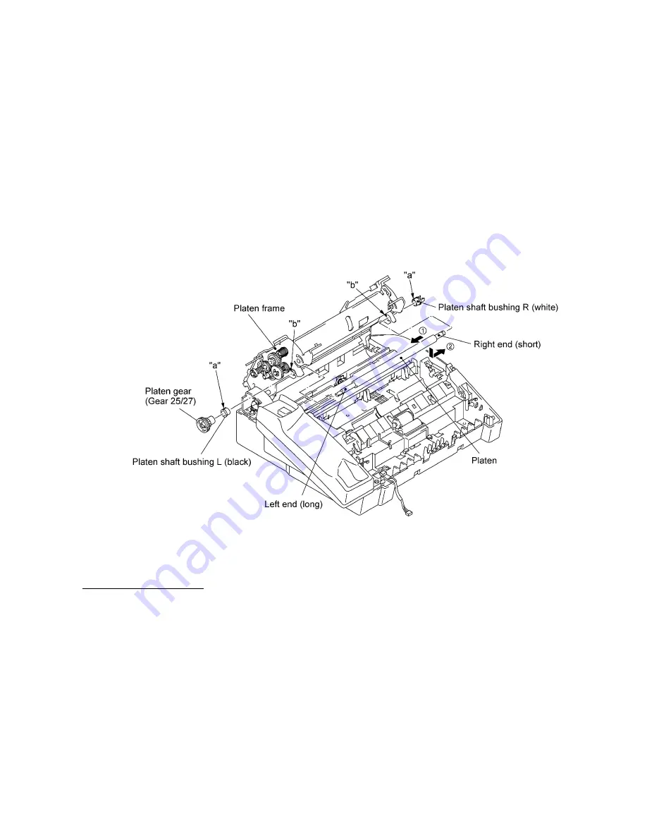
(16) Remove the platen as follows:
At the left end of the platen frame, remove the platen gear (gear 25/27) by pulling its pawl
outwards and then remove the platen shaft bushing L.
At the right end, remove the platen shaft bushing R by pulling its pawls outwards.
Move the platen to the left to take out the right end from the platen frame and then take it out to
the right.
CAUTION:
After removing the platen, NEVER close the platen frame ASSY when the
recording head ASSY is set in place. Doing so will make the cutouts of the platen frame ASSY
catch the right and left ends of the recording head ASSY. The platen frame ASSY and the
recording head ASSY will be locked together.
NOTE:
The platen shaft bushings are greased for antistatic purpose. Take care not to stain
other parts with the grease.
n
n
Reassembling Notes
•
If you replace the platen shaft bushing(s) with new one(s), apply grease to it. (Refer to Section
2, "LUBRICATION."
•
When reinstalling the platen shaft bushings R and L, fit boss "a" of each bushing into cutout "b"
provided in the platen frame. (See the above illustration.)
•
When attaching the chute film, align its rear edge with the rib of the paper feed chute.
•
When reinstalling the pressure plate, slide the ribs along the grooves of the paper feed chute
until the latches of the pressure plate catch the pressure plate link.
•
When setting the lock levers back into place, as shown on page IV-23, first fit the shorter end of
the spring into the cutout provided in each lock lever, then fit the longer end of the spring and the
lock lever's boss into the small and large holes provided in the platen frame, respectively. Fully
turn the lever to the rear so that the lever's hooks catch the platen frame.
Summary of Contents for FAX 750
Page 4: ...CHAPTER I GENERAL DESCRIPTION ...
Page 11: ...CHAPTER II INSTALLATION ...
Page 12: ...CHAPTER III THEORY OF OPERATION ...
Page 14: ...III 1 1 OVERVIEW Not provided on the FAX 910 ...
Page 24: ...III 11 Active Gears on the Inner Side of the Drive Unit ...
Page 26: ...III 13 Active Gears on the Inner Side of the Drive Unit ...
Page 30: ...III 17 Location of Sensors and Actuators 1 ...
Page 31: ...III 18 Not provided on the FAX 910 Location of Sensors and Actuators 2 ...
Page 34: ...III 21 FAX750 FAX770 FAX 910 FAX 920 FAX 921 MFC 925 FAX870MC FAX 930 FAX 931 MFC970MC ...
Page 39: ...CHAPTER IV DISASSEMBLY REASSEMBLY LUBRICATION AND ADJUSTMENT ...
Page 44: ...IV 4 n n Disassembly Order Flow ...
Page 48: ...IV 8 4 Disconnect the panel main harness ...
Page 52: ...IV 12 ...
Page 70: ...IV 30 Remove the two screws and lift up the paper feed chute ...
Page 72: ...IV 32 ...
Page 78: ...IV 38 ...
Page 86: ...IV 46 1 17 Harness Routing ...
Page 88: ...IV 48 ...
Page 89: ...IV 49 2 LF roller ASSY 3 Platen frame ASSY ...
Page 90: ...IV 50 ...
Page 91: ...IV 51 4 Separation roller and main frame ...
Page 92: ...CHAPTER V MAINTENANCE MODE ...
Page 99: ...V 6 Scanning Compensation Data List ...
Page 150: ...CHAPTER VI ERROR INDICATION AND TROUBLESHOOTING ...
Page 168: ...July 98 5X4401 Printed in Japan ...
Page 177: ......
Page 178: ......
Page 182: ......
Page 184: ......
Page 197: ......
Page 198: ......
Page 202: ......
Page 216: ......
Page 218: ......


