IV
- 37
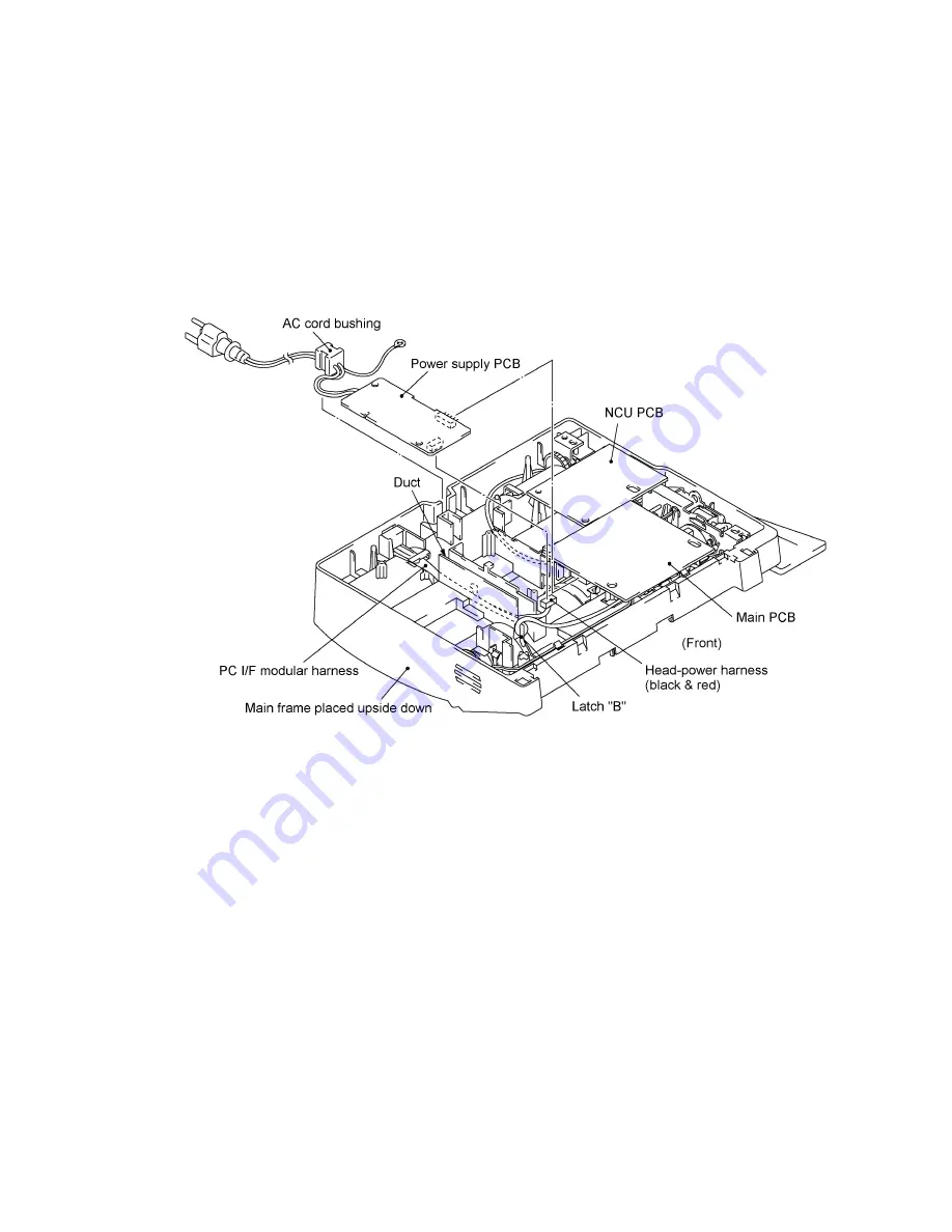
1.10 Power Supply PCB, Main PCB, and NCU PCB
(1) Unhook the head-power harness from latch "B" (together with the PC I/F modular harness
since the head-power harness is routed under the PC I/F modular harness through the duct
when viewed from the bottom).
(2) Pull out the AC cord bushing from the main frame.
(3) Disconnect the power supply PCB from the main PCB.
(4) Slightly lift up the power supply PCB and disconnect the head-power harness.
(5) Slightly lift up the main PCB and NCU PCB together, then disconnect the NCU PCB from the
main PCB.
(6) Disconnect the following nine harnesses from the main PCB:
• Hook switch harness (Not provided on the FAX-910.)
• Speaker harness
• Panel-main harness
• PC I/F modular harness
• CIS harness
• Solenoid harness
• Motor harness
• Main-head harness
• Main-sensor harness
NOTE:
The FAX870MC/FAX-930/FAX-931/MFC970MC has a Ni-MH battery ASSY. Only
when you need to replace the main PCB, disconnect the battery harness. After installing a new
main PCB, you may need to make settings to be stored in the RAM. If you need to replace the
battery ASSY, do not disconnect the harness in this disassembly step. Doing so with the power
cord unplugged will lose the settings stored in the RAM. Refer to Section 1.1.
(7) You may take out the harnesses (except for the main-head harness that is routed under the
drive unit) from the main frame.
Summary of Contents for FAX 750
Page 4: ...CHAPTER I GENERAL DESCRIPTION ...
Page 11: ...CHAPTER II INSTALLATION ...
Page 12: ...CHAPTER III THEORY OF OPERATION ...
Page 14: ...III 1 1 OVERVIEW Not provided on the FAX 910 ...
Page 24: ...III 11 Active Gears on the Inner Side of the Drive Unit ...
Page 26: ...III 13 Active Gears on the Inner Side of the Drive Unit ...
Page 30: ...III 17 Location of Sensors and Actuators 1 ...
Page 31: ...III 18 Not provided on the FAX 910 Location of Sensors and Actuators 2 ...
Page 34: ...III 21 FAX750 FAX770 FAX 910 FAX 920 FAX 921 MFC 925 FAX870MC FAX 930 FAX 931 MFC970MC ...
Page 39: ...CHAPTER IV DISASSEMBLY REASSEMBLY LUBRICATION AND ADJUSTMENT ...
Page 44: ...IV 4 n n Disassembly Order Flow ...
Page 48: ...IV 8 4 Disconnect the panel main harness ...
Page 52: ...IV 12 ...
Page 70: ...IV 30 Remove the two screws and lift up the paper feed chute ...
Page 72: ...IV 32 ...
Page 78: ...IV 38 ...
Page 86: ...IV 46 1 17 Harness Routing ...
Page 88: ...IV 48 ...
Page 89: ...IV 49 2 LF roller ASSY 3 Platen frame ASSY ...
Page 90: ...IV 50 ...
Page 91: ...IV 51 4 Separation roller and main frame ...
Page 92: ...CHAPTER V MAINTENANCE MODE ...
Page 99: ...V 6 Scanning Compensation Data List ...
Page 150: ...CHAPTER VI ERROR INDICATION AND TROUBLESHOOTING ...
Page 168: ...July 98 5X4401 Printed in Japan ...
Page 177: ......
Page 178: ......
Page 182: ......
Page 184: ......
Page 197: ......
Page 198: ......
Page 202: ......
Page 216: ......
Page 218: ......