VI
- 1
1. ERROR INDICATION
To help the user or the service personnel promptly locate the cause of a problem (if any), the
facsimile equipment incorporates the self-diagnostic functions which display error messages for
equipment errors and communications errors.
For the communications errors, the equipment also prints out the transmission verification report
and the communications list.
1.1
Equipment Errors
If an equipment error occurs, the facsimile equipment emits an audible alarm (continuous beeping)
for approximately 4 seconds and shows the error message on the LCD. For the error messages,
see [ 1 ] below.
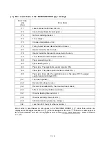
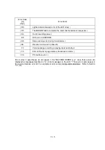
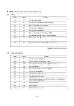
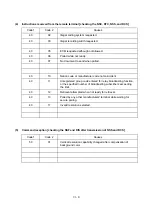
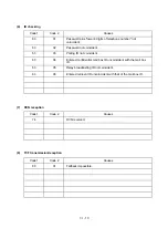
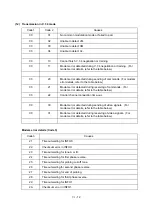
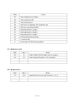
To display detailed error information, use the maintenance-mode function code 82 described in
Chapter V, Section 3.11 (that is, make the equipment enter the maintenance mode and then press
the
8
and
2
keys). Following the MACHINE ERROR, one of the error codes listed in [ 2 ] will
appear on the LCD.
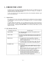
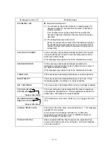
[ 1 ] Error messages on the LCD
Messages on the LCD
Probable Cause
CHECK PAPER
Even after paper pulling-in operation, the registration sensor
does not detect paper.
COVER OPEN
The cover sensor detects that the top cover is not closed or the
sheet feeder cover sensor detects that the sheet feeder cover is
not closed.
PRINTER JAM
(1) The paper ejection sensor stays OFF even after the
registration sensor has gone OFF and the paper has been
fed by the specified amount.
(2) The paper ejection sensor stays ON even after it has came
ON and the paper has been fed by the specified amount.
DOCUMENT JAM
n
Document jam
(1) The document length exceeds the limitation (400 or 90 cm)
registered by firmware switch WSW16. (Refer to Chapter V,
Section 3.5.)
(Both the document front and rear sensors stay ON after the
document has been fed by the registered length.)
(2) The document rear sensor detects no trailing edge of a
document after the document has been fed by 400 cm.
(The document rear sensor stays ON even after the
document has been fed when the document front and rear
sensors were OFF and ON, respectively.)
Summary of Contents for FAX-8650P
Page 1: ...FACSIMILE EQUIPMENT SERVICE MANUAL MODEL FAX3750 FAX 8650P MFC7750 ...
Page 5: ...CHAPTER I GENERAL DESCRIPTION ...
Page 12: ...CHAPTER II INSTALLATION ...
Page 13: ...CONTENTS 1 INSTALLING THE UPDATE DATA TO THE FACSIMILE EQUIPMENT II 1 ...
Page 16: ...CHAPTER III THEORY OF OPERATION ...
Page 18: ...III 1 1 OVERVIEW Not provided on the FAX 8650P ...
Page 28: ...III 11 Not provided on the FAX 8650P Location of Sensors and Actuators ...
Page 31: ...III 14 Main PCB Modem PCB ...
Page 36: ...CHAPTER IV DISASSEMBLY REASSEMBLY AND LUBRICATION ...
Page 42: ...IV 4 n n Disassembly Order Flow ...
Page 71: ...IV 33 1 Provided on the FAX 8650P 2 Not provided on the FAX 8650P ...
Page 72: ...IV 34 Setting up the main PCB after replacement ...
Page 84: ...IV 46 2 Control panel locks 3 Scanner frame ASSY and separation roller gear ...
Page 85: ...IV 47 4 Top cover lock spring 5 Gear drive unit ...
Page 86: ...CHAPTER V MAINTENANCE MODE ...
Page 93: ...V 6 Scanning Compensation Data List ...
Page 141: ...V 54 FAX3750 FAX 8650P MFC7750 Key Button Entry Order ...
Page 146: ...CHAPTER VI ERROR INDICATION AND TROUBLESHOOTING ...
Page 171: ...Oct 98 SM5X5303 Printed in Japan ...
Page 172: ...FAX3750 FAX 8650P MFC7750 Appendix 1 EEPROM Customizing Codes ...
Page 194: ......
Page 195: ......
Page 196: ......

