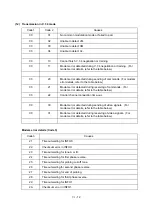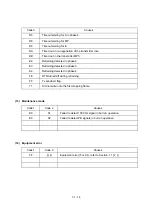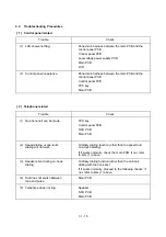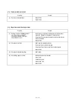
VI
- 2
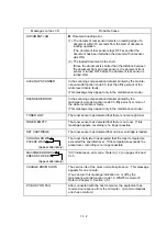
Messages on the LCD
Probable Cause
DOCUMENT JAM
n
Document loading error
(1) The document rear sensor detects no leading edge of a
document within 10 seconds from the start of document
loading operation.
(The document rear sensor stays OFF even after the
document has been fed when the document front sensor
was ON.)
(2) The loaded document is too short.
(Since the document is shorter than the distance between
the document front and rear sensors, the document front
sensor is turned OFF before the document rear sensor is
turned ON.)
CLEAN UP SCANNER
In the scanning compensation data list printed by the mainte-
nance-mode function code 05, less than fifty percent of the
white level data is faulty.
(This message may appear only in the maintenance mode.)
SCANNER ERROR
In the scanning compensation data list printed by the
maintenance-mode function code 05, fifty percent or more of
the white level data is faulty.
(This message may appear only in the maintenance mode.)
TONER LOW
The toner sensor has detected that there is not enough toner.
TONER EMPTY
The toner sensor has detected that there is no toner. If this
message appears, recording is no longer possible.
SET CARTRIDGE
The toner sensor has detected that no toner cartridge is loaded.
COOLING DOWN
PLEASE WAIT
(Appear alternately.)
The toner thermister has detected that the toner temperature
exceeded the specified level. If the temperature exceeds the
preset level, recording is no longer possible.
MACHINE ERROR XX
PRESS STOP KEY
(Appear alternately.)
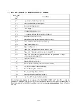
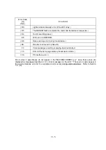
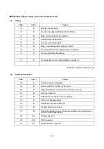
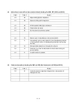
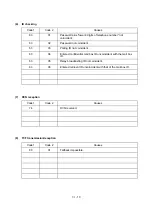
"XX" indicates an error code. Refer to [ 2 ] on pages VI-4 and
VI-5.
CHANGE DRUM SOON
The service life of the drum unit will expire soon. This message
appears for one minute.
(You can turn this message indication on or off by the
maintenance-mode function code 10, WSW30, selector 8.
Refer to Chapter V, Section 3.5.)
PC BUSY OR FAIL
After connected with the host computer, the equipment has
received no response from the computer. (A communications
error has occurred.)
Summary of Contents for FAX-8650P
Page 1: ...FACSIMILE EQUIPMENT SERVICE MANUAL MODEL FAX3750 FAX 8650P MFC7750 ...
Page 5: ...CHAPTER I GENERAL DESCRIPTION ...
Page 12: ...CHAPTER II INSTALLATION ...
Page 13: ...CONTENTS 1 INSTALLING THE UPDATE DATA TO THE FACSIMILE EQUIPMENT II 1 ...
Page 16: ...CHAPTER III THEORY OF OPERATION ...
Page 18: ...III 1 1 OVERVIEW Not provided on the FAX 8650P ...
Page 28: ...III 11 Not provided on the FAX 8650P Location of Sensors and Actuators ...
Page 31: ...III 14 Main PCB Modem PCB ...
Page 36: ...CHAPTER IV DISASSEMBLY REASSEMBLY AND LUBRICATION ...
Page 42: ...IV 4 n n Disassembly Order Flow ...
Page 71: ...IV 33 1 Provided on the FAX 8650P 2 Not provided on the FAX 8650P ...
Page 72: ...IV 34 Setting up the main PCB after replacement ...
Page 84: ...IV 46 2 Control panel locks 3 Scanner frame ASSY and separation roller gear ...
Page 85: ...IV 47 4 Top cover lock spring 5 Gear drive unit ...
Page 86: ...CHAPTER V MAINTENANCE MODE ...
Page 93: ...V 6 Scanning Compensation Data List ...
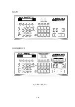
Page 141: ...V 54 FAX3750 FAX 8650P MFC7750 Key Button Entry Order ...
Page 146: ...CHAPTER VI ERROR INDICATION AND TROUBLESHOOTING ...
Page 171: ...Oct 98 SM5X5303 Printed in Japan ...
Page 172: ...FAX3750 FAX 8650P MFC7750 Appendix 1 EEPROM Customizing Codes ...
Page 194: ......
Page 195: ......
Page 196: ......


