


V
- 50
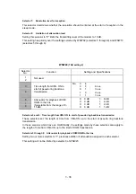
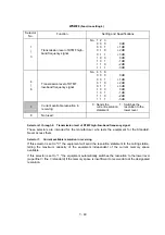
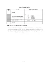
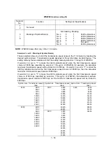
WSW40
(Function setting 18)
Selector
No.
Function
Setting and Specifications
1
2
Not used.
3
|
8
Masking of Symbol Rate(s)
Not masking Masking
No. 3
0
1
3429 symbols/sec
No. 4
0
1
3200 symbols/sec
No. 5
0
1
3000 symbols/sec
No. 6
0
1
2800 symbols/sec
No. 7
-
-
Not used.
No. 8
0
1
2400 symbols/sec
NOTE:
WSW40 takes effect only in the V. 34 mode.
l
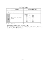
Selectors 3 and 8: Masking of Symbol Rate(s)
These selectors allow you to limit the transmission speed range in the V. 34 mode by masking the
desired symbol rate(s). Transmission speeds assigned to the symbol rates are listed below. The
setting made by these selectors will limit the setting made by selectors 1 through 4 of WSW39.
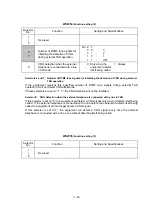
If selector 3 is set to "1" to mask the 3429 symbols/second when the first transmission speed
choice is 33600 bps (specified by selectors 1 through 4 of WSW39), for example, the allowable
maximum transmission speed will be limited to 31200 bps. If selector 8 is set to "1" to mask the
2400 symbols/second when the first transmission speed choice is 33600 bps, then the allowable
maximum transmission speed remains 33600 bps.
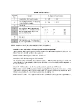
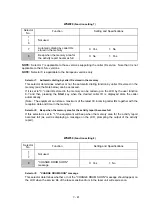
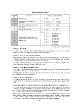
If selector 8 is set to "1" to mask the 2400 symbols/second when the first transmission speed
choice is 21600 bps (specified by selectors 1 through 4 of WSW39), the allowable maximum
transmission speed remains 21600 bps but the minimum transmission speed will be limited to
4800 bps.
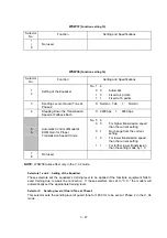
Symbol rate
Transmission speed
(bps)
Symbol rate Transmission speed
(bps)
Symbol rate Transmission speed
(bps)
2400
2400
3000
4800
3429
4800
4800
7200
7200
7200
9600
9600
9600
12000
12000
12000
14400
14400
14400
16800
16800
16800
19200
19200
19200
21600
21600
21600
24000
24000
2800
4800
26400
28800
7200
28800
31200
9600
3200
4800
33600
12000
7200
14400
9600
16800
12000
19200
14400
21600
16800
24000
19200
26400
21600
24000
26400
28800
31200
Summary of Contents for FAX-8650P
Page 1: ...FACSIMILE EQUIPMENT SERVICE MANUAL MODEL FAX3750 FAX 8650P MFC7750 ...
Page 5: ...CHAPTER I GENERAL DESCRIPTION ...
Page 12: ...CHAPTER II INSTALLATION ...
Page 13: ...CONTENTS 1 INSTALLING THE UPDATE DATA TO THE FACSIMILE EQUIPMENT II 1 ...
Page 16: ...CHAPTER III THEORY OF OPERATION ...
Page 18: ...III 1 1 OVERVIEW Not provided on the FAX 8650P ...
Page 28: ...III 11 Not provided on the FAX 8650P Location of Sensors and Actuators ...
Page 31: ...III 14 Main PCB Modem PCB ...
Page 36: ...CHAPTER IV DISASSEMBLY REASSEMBLY AND LUBRICATION ...
Page 42: ...IV 4 n n Disassembly Order Flow ...
Page 71: ...IV 33 1 Provided on the FAX 8650P 2 Not provided on the FAX 8650P ...
Page 72: ...IV 34 Setting up the main PCB after replacement ...
Page 84: ...IV 46 2 Control panel locks 3 Scanner frame ASSY and separation roller gear ...
Page 85: ...IV 47 4 Top cover lock spring 5 Gear drive unit ...
Page 86: ...CHAPTER V MAINTENANCE MODE ...
Page 93: ...V 6 Scanning Compensation Data List ...
Page 141: ...V 54 FAX3750 FAX 8650P MFC7750 Key Button Entry Order ...
Page 146: ...CHAPTER VI ERROR INDICATION AND TROUBLESHOOTING ...
Page 171: ...Oct 98 SM5X5303 Printed in Japan ...
Page 172: ...FAX3750 FAX 8650P MFC7750 Appendix 1 EEPROM Customizing Codes ...
Page 194: ......
Page 195: ......
Page 196: ......


