


HE-800B
3. INSTALLATION
10
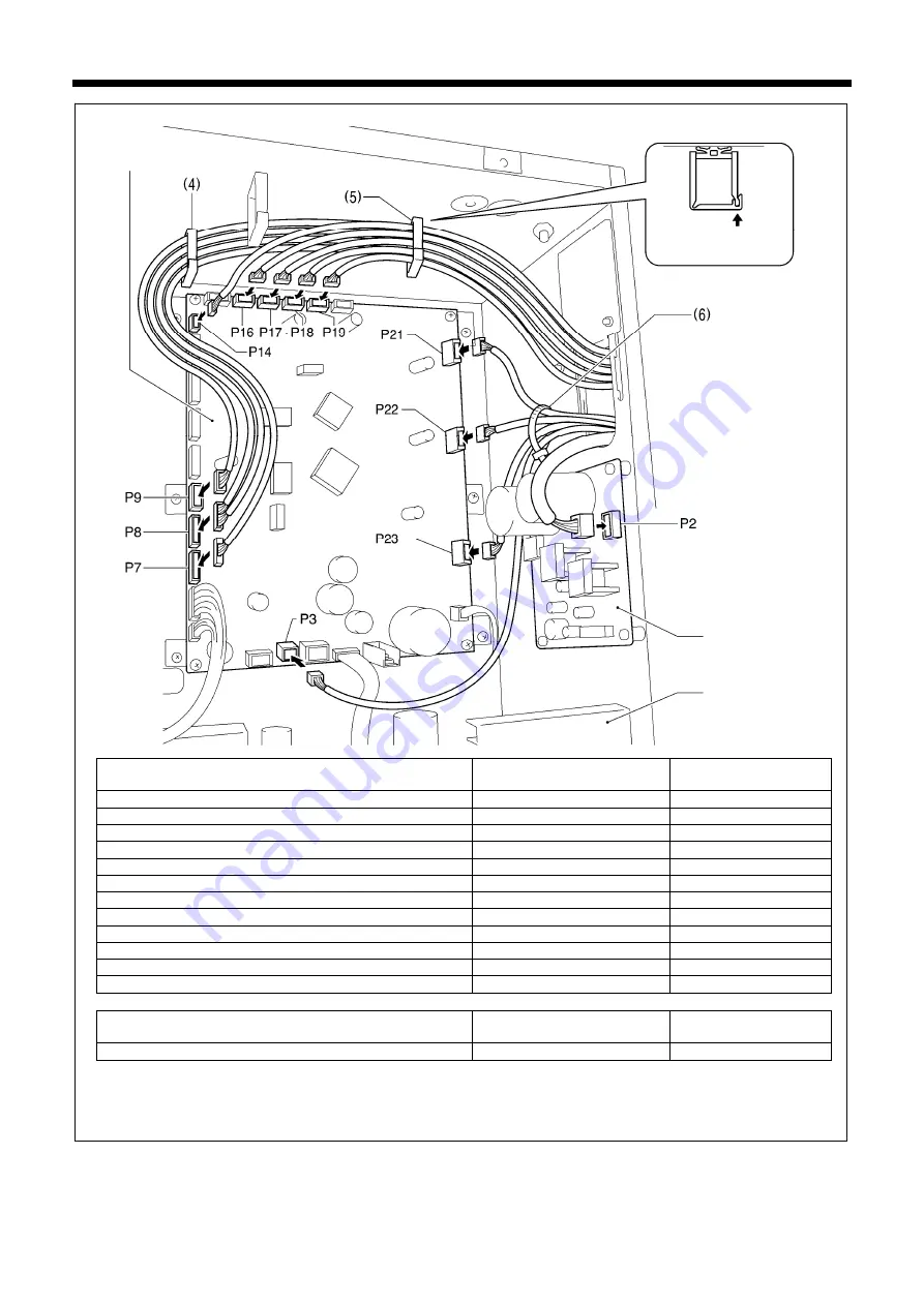
Connector
Connection location on main
P.C. board
Cord clamp
Cutter sensor 6-pin
P7 (SENSOR2)
(4) (5)
Feed sensor, thread breakage sensor 12-pin
P8 (SENSOR1)
(4) (5)
STOP switch 6-pin
P9 (HEAD)
(4) (5)
Safety switch 3-pin
P14 (HEAD-SW)
(5)
Machine head memory 6-pin
P16 (HEAD-MEM)
(5)
Needle zigzag sensor, needle zigzag encoder 5-pin white
P17 (X-ENC)
(5)
Feed encoder 5-pin blue
P18 (Y-ENC)
(5)
Work clamp sensor, work clamp encoder 5-pin black
P19 (P-ENC)
(5)
Needle zigzag motor 4-pin white
P21 (XPM)
(6)
Feed motor 4-pin blue
P22 (YPM)
(6)
Work clamp motor 4-pin black
P23 (PPM)
(6)
Tension release solenoid 4-pin
P3 (SOL2)
(6)
Connector
Connection location on
cutter P.C. board
Cord clamp
Cutter solenoid 4-pin
P2 (SOL)
–
NOTE:
Route the needle zigzag, feed and work clamp motor harnesses and the tension release solenoid harness so
that they do not touch the cutter P.C. board and the power supply P.C. board.
(Continued on next page)
Lock the cord
clamp securely.
<Main P.C. board>
<Power supply P.C.
board>
<Cutter P.C. board>
4746M


