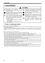

7. ADJUSTMENT
HE-800B
93
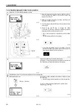
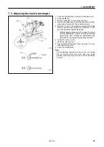
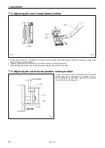
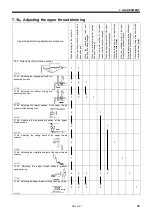
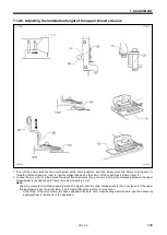
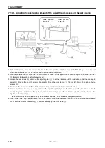
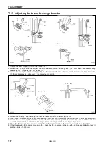
7-8. Adjusting the work clamp lateral position
1. Loosen the set screw (1), and then move the feed arm (2) and the roller (3) to adjust so that the knife groove comes to the
center of the work clamp window.
2. Operate the treadle and check that the work clamp moves up and down smoothly.
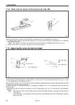
* After adjusting, check the upper thread trimmer mechanism and adjust if necessary.
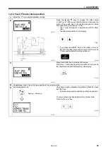
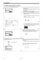
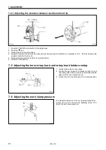
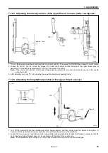
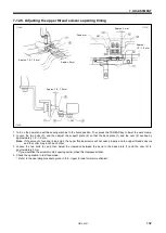
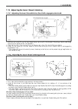
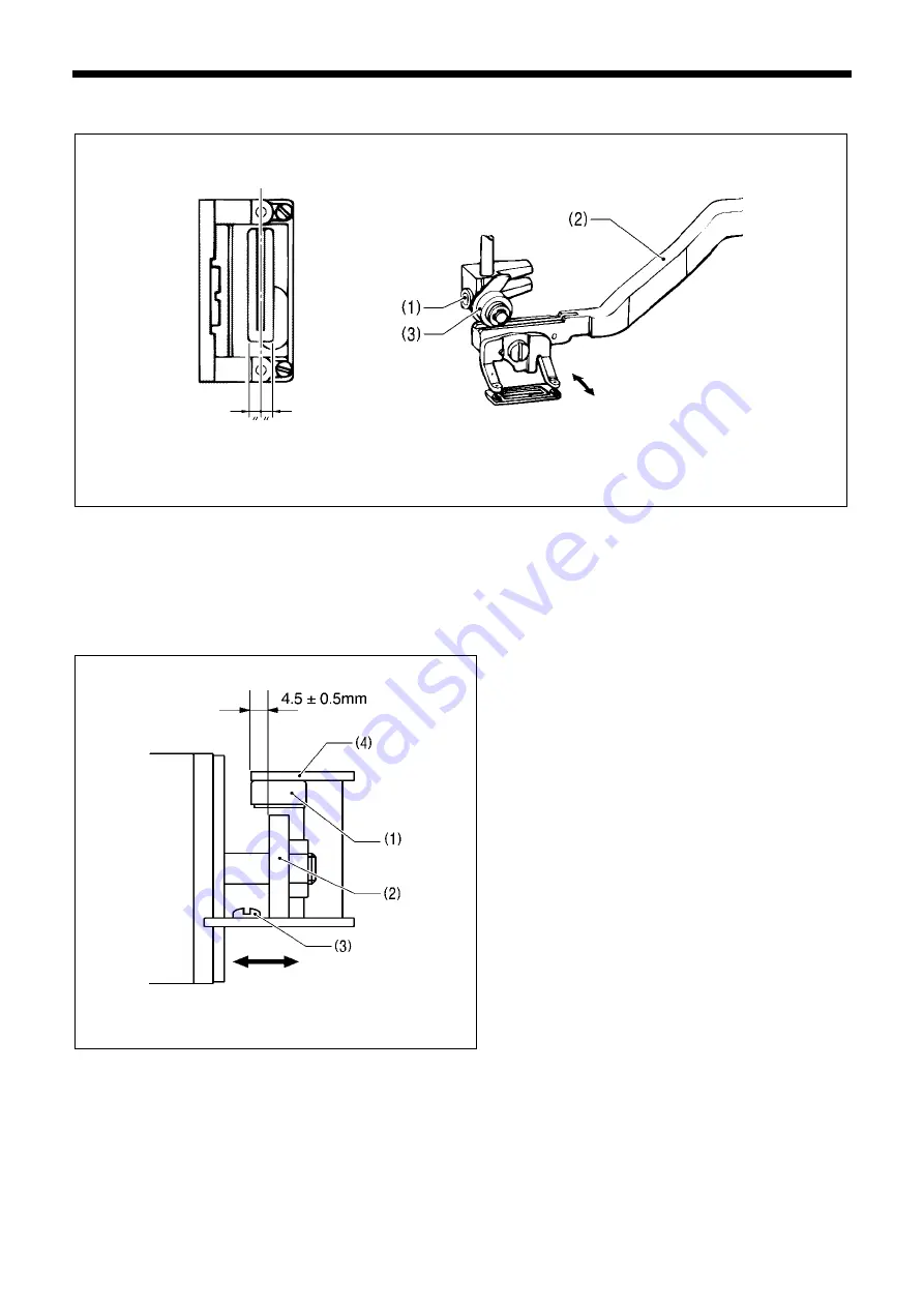
7-9. Adjusting the cutter home position sensor position
Loosen the screw (3), and then adjust the cutter sensor
setting plate (4) so that there is a clearance of 4.5 ±
0.5 mm between the side of the cutter sensor (1) and the
edge of the solenoid stopper (2).
4300Q
4299Q
4301Q
Summary of Contents for HE-800B
Page 7: ...v HE 800B Oil tank accessory 4732M 4731M 4730M ...
Page 75: ...6 ASSEMBLY HE 800B 66 D E 0688D 0690D ...
Page 126: ...9 ELECTRIC MECHANISM HE 800B 117 Power PCB Cutter PCB LCD panel PCB 0831D 0768D 0769D ...
Page 133: ...9 ELECTRIC MECHANISM HE 800B 124 0851D ...
Page 134: ...9 ELECTRIC MECHANISM HE 800B 125 0852D ...
Page 135: ...9 ELECTRIC MECHANISM HE 800B 126 0853D ...
Page 177: ...MEMO 168 HE 800B ...
Page 178: ...SERVICE MANUAL 2014 Brother Industries Ltd All Rights Reserved HE 800B I3061003D 2014 03 D 1 ...


