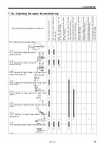
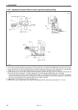
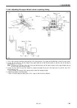
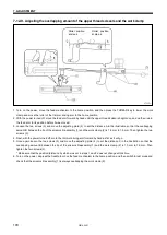

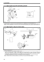
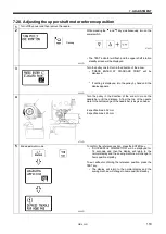
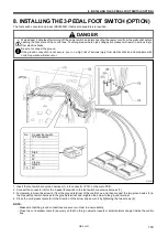
7. ADJUSTMENT
HE-800B
107
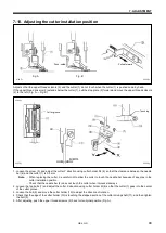
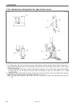
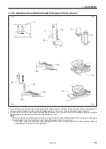
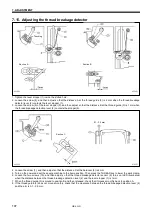
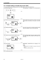
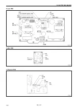
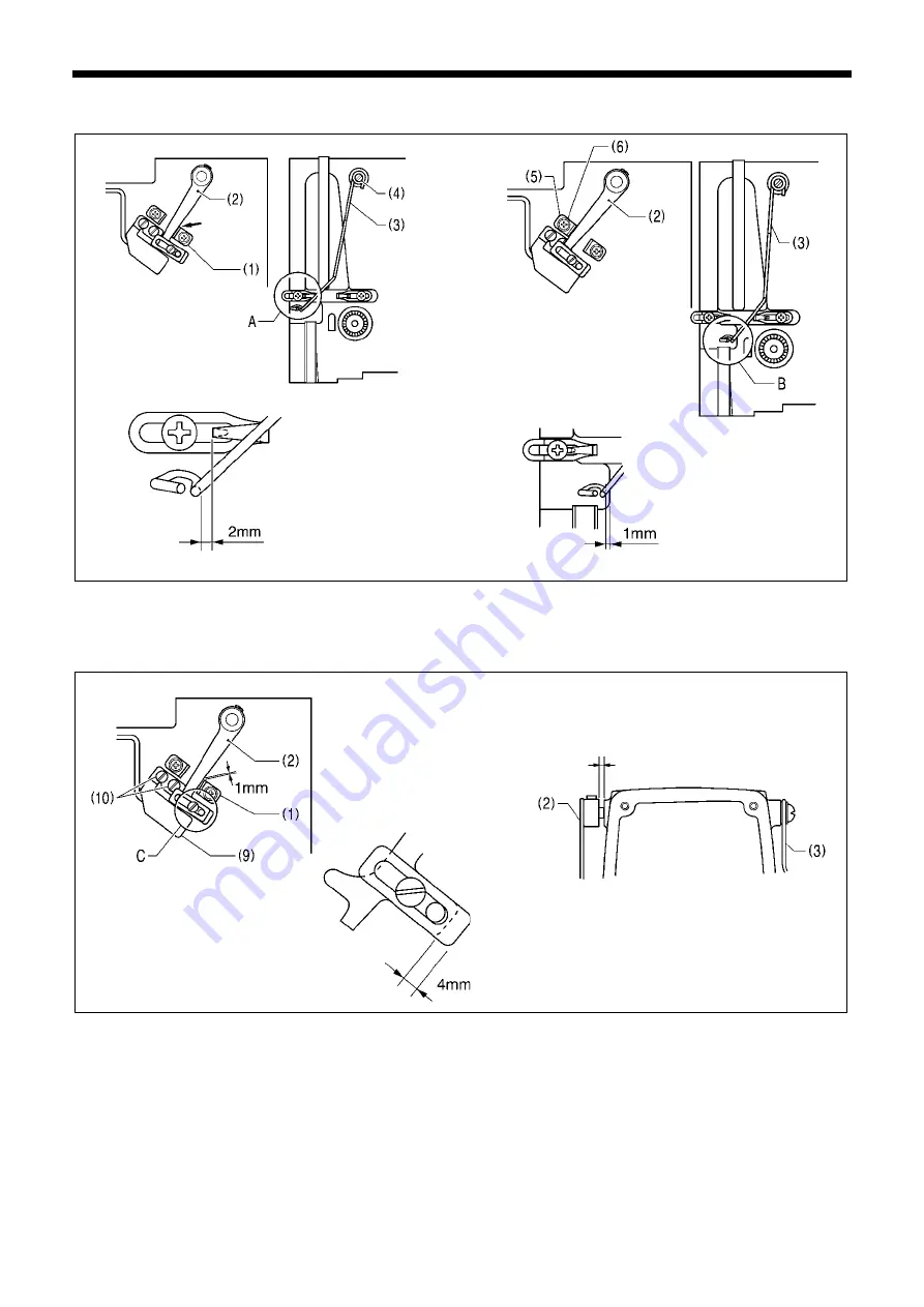
7-15. Adjusting the thread breakage detector
1. Tighten the lever stopper (1) inside the slotted hole.
2. Loosen the screw (4), and then adjust so that the distance A at the thread guide (3) is 2 mm when the thread breakage
detector lever (2) contacts the lever stopper (1).
3. Loosen the screw (6) of the lever stopper (5), and then adjust so that the distance B at the thread guide (3) is 1 mm when
the thread breakage detection lever (2) contacts the stopper (5).
4. Loosen the screw (7), and then adjust so that the distance C at the balancer (8) is 4 mm.
5. Turn on the power and set the sewing machine to the home position. Then press the THREAD key to lower the work clamp.
6. Loosen the two screws (10), and then adjust so that the thread breakage detector sensor (9) turns on (LED illuminates)
when the distance between the thread breakage detection lever (2) and the lever stopper (1) is 1 mm.
7. When the thread guide (3) is moved to position B and then released, check that it moves smoothly back to position A.
8. If the thread guide (3) does not move smoothly, check that the clearance between the thread breakage detection lever (2)
and the arm is 0.1 - 0.5 mm.
4354Q
4353Q
4355Q
0743D
0.1 - 0.5 mm
Section A
Touching
Section B
Section C
Summary of Contents for HE-800B
Page 7: ...v HE 800B Oil tank accessory 4732M 4731M 4730M ...
Page 75: ...6 ASSEMBLY HE 800B 66 D E 0688D 0690D ...
Page 126: ...9 ELECTRIC MECHANISM HE 800B 117 Power PCB Cutter PCB LCD panel PCB 0831D 0768D 0769D ...
Page 133: ...9 ELECTRIC MECHANISM HE 800B 124 0851D ...
Page 134: ...9 ELECTRIC MECHANISM HE 800B 125 0852D ...
Page 135: ...9 ELECTRIC MECHANISM HE 800B 126 0853D ...
Page 177: ...MEMO 168 HE 800B ...
Page 178: ...SERVICE MANUAL 2014 Brother Industries Ltd All Rights Reserved HE 800B I3061003D 2014 03 D 1 ...