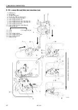
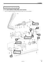
6. ASSEMBLY
HE-800B
53
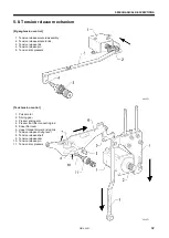
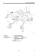
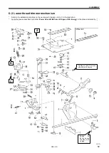
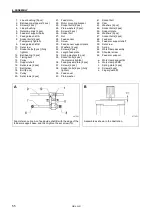
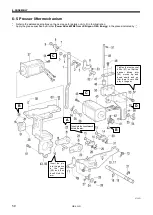
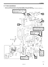
1. Lower thread trimming cam
connecting rod
2. Driving lever roller
3. Shoulder screw
4. Lower thread trimmer cam
5. Lever shaft
6. Set screw
7. Roller shaft
8. Nut
9. Roller
10. Retaining ring
11. Lower thread trimmer cam
lever
12. Cam shaft, ;L-TR
13. Washer
14. Retaining ring
15. Set screw
16. Cover
17. Lower thread trimmer link
18. Shoulder screw
19. Shoulder screw
20. Screw
21. Opening plate, B
22. Screw
23. Shoulder screw
24. Roller
25. Roller shaft
26. Opening plate, A
27. Shoulder screw
28. Spring
29. Screw
30. Lever assembly
31. Collar
32. Lower thread retainer
33. Screws [2 pcs]
34. Screw
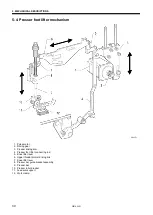
35. Knife driving lever
36. Collar
37. Plain washer D
38. Plain washer U
39. Shoulder screw
40. Lower thread clamp plate
assembly
41. Washer
42. Plain washer
43. Shoulder screw, SM3.18
44. Lower thread presser
45. Shoulder screw
46. Screw
47. Lower fixed knife assy
48. Movable knife assy
49. Washer
50. Plain washer
51. Bind
52. Bind
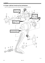
53. Needle plate
54. Flat screws [2 pcs]
55. Base plate
56. Screws [4 pcs]
57. Spring hook U
58. Bobbin presser bracket
59. Screw
60. Nut
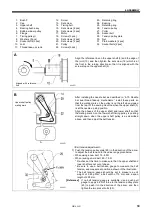
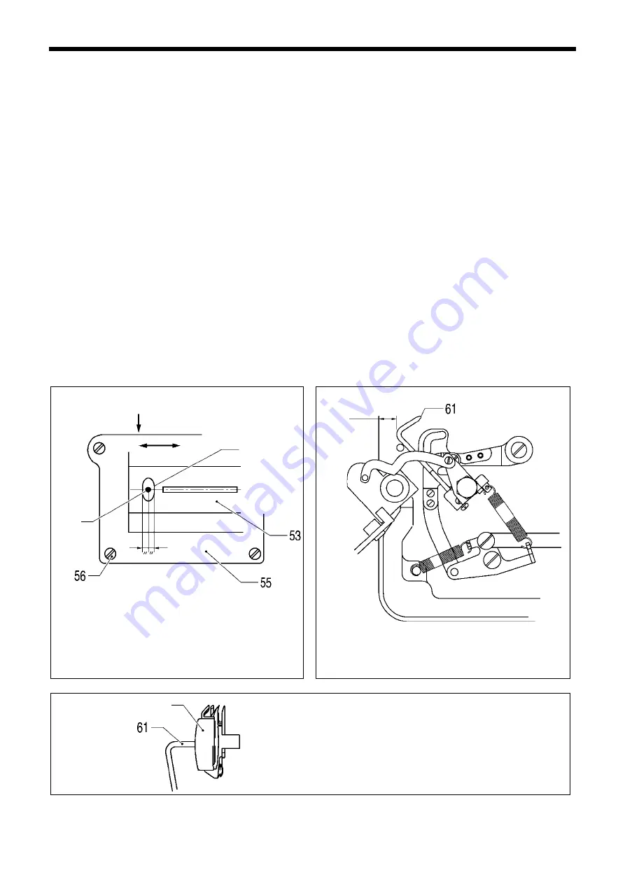
61. Bobbin presser
62. Screw
63. Auxiliary plate
64. Opening plate
65. Shoulder screw
66. Shoulder screw
67. Shoulder screw
68. Shoulder screw
69. Spring [2 pcs]
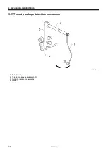
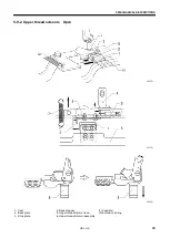
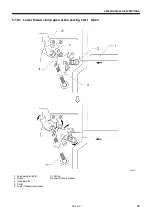
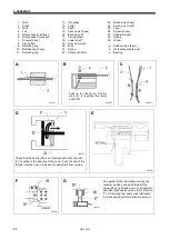
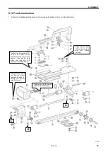
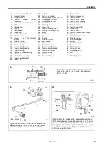
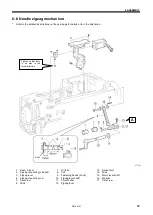
a.
Lower thread trimmer link assy
A
b. Lower thread connecting rod A
c. Screws [2 pcs]
d. Needle plate cover
e. Base plate
A
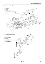
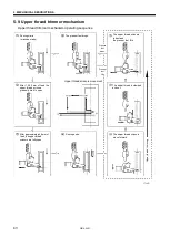
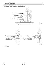
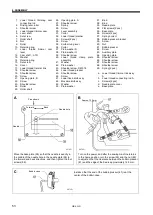
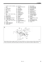
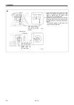
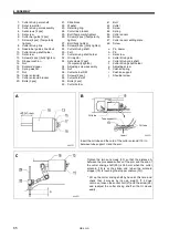
Move the base plate (55) so that the needle is exactly in
the middle of the needle hole in the needle plate (53) in
the forward and back directions, and then tighten the four
screws (56).
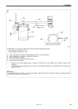
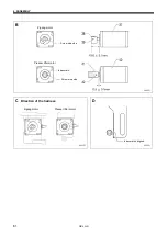
B
Turn on the power, and after the sewing machine returns
to the home position, turn the screw (59) and the nut (60)
to adjust so that the clearance between the bobbin presser
(61) and the edge of the bed is approximately 12.5 mm.
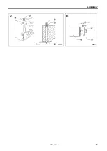
C
Install so that the end of the bobbin presser (61) is at the
center of the bobbin case.
0671D
Bobbin case
0670D
Needle
Needle hole
0672D
Approx.12.5 mm
Press down
Forward
Back
Summary of Contents for HE-800B
Page 7: ...v HE 800B Oil tank accessory 4732M 4731M 4730M ...
Page 75: ...6 ASSEMBLY HE 800B 66 D E 0688D 0690D ...
Page 126: ...9 ELECTRIC MECHANISM HE 800B 117 Power PCB Cutter PCB LCD panel PCB 0831D 0768D 0769D ...
Page 133: ...9 ELECTRIC MECHANISM HE 800B 124 0851D ...
Page 134: ...9 ELECTRIC MECHANISM HE 800B 125 0852D ...
Page 135: ...9 ELECTRIC MECHANISM HE 800B 126 0853D ...
Page 177: ...MEMO 168 HE 800B ...
Page 178: ...SERVICE MANUAL 2014 Brother Industries Ltd All Rights Reserved HE 800B I3061003D 2014 03 D 1 ...


