6. ASSEMBLY
HE-800B
63
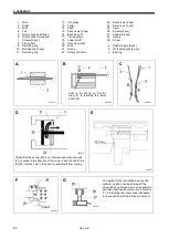
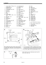
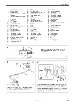
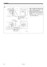
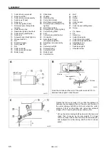
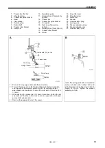
A
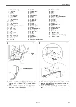
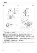
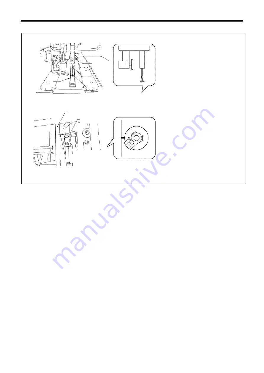
1) Install the needle to the needle bar, and
secure it in position so that the tip of the
needle is aligned with the center of the
cutter groove in the needle plate.
2) Tighten the socket bolt (13) at the position
where the index hole in the motor lever and
the reference line on the motor bracket are
aligned.
* At this time, tighten so that there is no
play in the thrust direction.
0683D
0684D
Align the center of
the cutter groove
and the tip of the
needle.
Motor bracket
Motor lever
Align the reference
line on the motor
bracket and the
index hole in
the motor lever.
Summary of Contents for HE-800B
Page 7: ...v HE 800B Oil tank accessory 4732M 4731M 4730M ...
Page 75: ...6 ASSEMBLY HE 800B 66 D E 0688D 0690D ...
Page 126: ...9 ELECTRIC MECHANISM HE 800B 117 Power PCB Cutter PCB LCD panel PCB 0831D 0768D 0769D ...
Page 133: ...9 ELECTRIC MECHANISM HE 800B 124 0851D ...
Page 134: ...9 ELECTRIC MECHANISM HE 800B 125 0852D ...
Page 135: ...9 ELECTRIC MECHANISM HE 800B 126 0853D ...
Page 177: ...MEMO 168 HE 800B ...
Page 178: ...SERVICE MANUAL 2014 Brother Industries Ltd All Rights Reserved HE 800B I3061003D 2014 03 D 1 ...

