HE-800B
CONTENTS
1. SPECIFICATIONS .................................
1
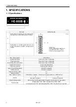
1-1.
Specifications .......................................................... 1
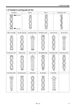
1-2.
Standard sewing pattern list .................................... 2
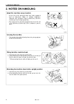
2. NOTES ON HANDLING .........................
3
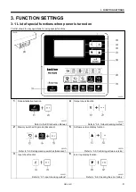
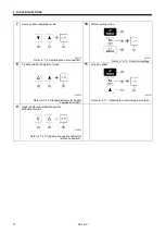
3. FUNCTION SETTINGS ..........................
4
3-1.
List of special functions when power is turned
on ........................................................................... 4
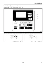
3-2.
List of advanced functions ..................................... 6
3-3.
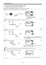
Setting memory switches (Advanced) .................... 7
3-4.
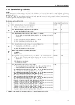
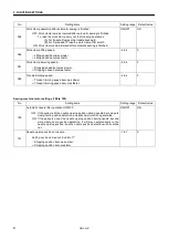
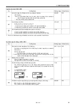
List of memory switches ......................................... 8
3-5.
Pedal operation mode setting method ................. 14
3-6.
Checking the error history .................................... 16
3-7.
Input checking method ......................................... 17
3-8.
Output checking method ...................................... 20
3-9.
Confirming software version................................. 22
3-10.
Protection settings ............................................. 23
4. USING SD CARDS ..............................
26
4-1.
Notes on handling SD cards
(commercially available) ...................................... 26
4-2.
Structure of an SD card folder.............................. 26
4-3.
Preparation for reading and writing data .............. 27
4-4.
Reading program data (parameters) .................... 28
4-5.
Writing program data (parameters) to an SD
memory card ........................................................ 29
4-6.
Reading memory switch data ............................... 30
4-7.
Writing memory switch data to the SD card ......... 31
4-8.
Reading sewing machine data ............................. 32
4-9.
Writing sewing machine data to an SD card ........ 33
4-10.
Writing error log data to an SD card .................. 34
4-11.
Updating the control program version ................ 35
5. MECHANICAL DESCRIPTIONS .........
36
5-1.
Needle bar and thread take-up mechanisms ....... 36
5-2.
Upper shaft, lower shaft and rotary hook
mechanisms ......................................................... 37
5-3.
Needle zigzag mechanism ................................... 38
5-4.
Presser foot lifter mechanism............................... 39
5-5.
Feed mechanism ................................................. 40
5-6.
Cutter mechanism ................................................ 40
5-7.
Thread breakage detection mechanism ............... 41
5-8.
Tension release mechanism ................................ 42
5-9.
Upper thread trimmer mechanism ........................ 43
5-9-1. Upper thread scissors
Gradually opens ...... 45
5-9-2. Upper thread scissors
Open ....................... 46
5-10.
Lower thread trimmer mechanism ...................... 47
5-10-1. Lower thread clamp open at the sewing start
Open ················································ 48
6. ASSEMBLY ..........................................
49
6-1.
Lower shaft and idle pulley mechanisms ............. 50
6-2.
Lower thread trimmer mechanism ....................... 52
6-3.
Feed mechanism ................................................. 54
6-4.
Threading mechanism ......................................... 57
6-5.
Presser lifter mechanism ..................................... 59
6-6.
Needle zigzag mechanism ................................... 62
6-7.
Cutter mechanism ............................................... 64
6-8.
Upper shaft and tension pulley mechanisms ....... 67
6-9.
Lubrication mechanism ........................................ 69
6-10.
Needle bar and thread take-up mechanisms ..... 75
6-11.
Presser bar mechanism .................................... 77
6-12.
Upper thread trimmer mechanism ..................... 79
6-13.
Thread breakage detector mechanism .............. 80
6-14.
Rotary hook mechanism .................................... 81
6-15.
Covers ............................................................... 82
7. ADJUSTMENT ......................................
83
7-1.
Notes on making adjustments ............................. 83
7-2.
Adjusting the home position ................................. 84
7-2-1. Switching to home position adjustment
mode............................................................. 84
7-2-2. Needle zigzag (X) motor home position ........ 85
7-2-3. Feed (Y) motor home position ....................... 86
7-2-4. Work clamp (P) motor home position ............ 87
7-3.
Adjusting the needle bar height ........................... 88
7-4.
Adjusting the needle and hook timing .................. 89
7-4-1. Adjusting the clearance between needle
and hook tip .................................................. 91
7-5.
Adjusting the inner rotary hook and rotary hook
holder overlap ...................................................... 91
7-6.
Adjusting the work clamp pressure ...................... 91
7-7.
Adjusting the work clamp lift amount ................... 92
7-8.
Adjusting the work clamp lateral position ............. 93
7-9.
Adjusting the cutter home position sensor
position ................................................................ 93
7-10.
Adjusting the cutter installation position............. 94
7-10-1. When using the special needle plate
(needle plate -RB) ..................................... 95
7-11.
Adjusting the cutter installation height ............... 95
7-12.
Adjusting the upper thread trimming .................. 96
7-12-1. Adjusting the longitudinal feed arm
assembly position ....................................... 97
7-12-2. Adjusting the trimmer driving arm
assembly position ....................................... 97
7-12-3. Adjusting the lateral position of the upper
thread scissors at the sewing start .............. 98
7-12-4. Adjusting the longitudinal position of the
upper thread scissors.................................. 98
Summary of Contents for HE-800B
Page 7: ...v HE 800B Oil tank accessory 4732M 4731M 4730M ...
Page 75: ...6 ASSEMBLY HE 800B 66 D E 0688D 0690D ...
Page 126: ...9 ELECTRIC MECHANISM HE 800B 117 Power PCB Cutter PCB LCD panel PCB 0831D 0768D 0769D ...
Page 133: ...9 ELECTRIC MECHANISM HE 800B 124 0851D ...
Page 134: ...9 ELECTRIC MECHANISM HE 800B 125 0852D ...
Page 135: ...9 ELECTRIC MECHANISM HE 800B 126 0853D ...
Page 177: ...MEMO 168 HE 800B ...
Page 178: ...SERVICE MANUAL 2014 Brother Industries Ltd All Rights Reserved HE 800B I3061003D 2014 03 D 1 ...


