6. ASSEMBLY
HE-800B
78
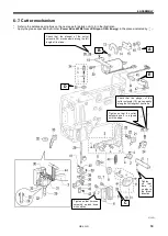
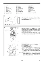
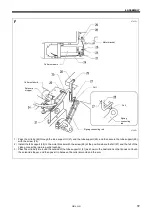
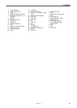
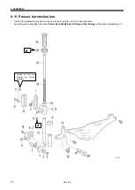
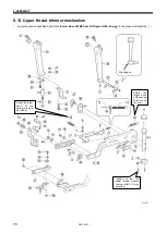
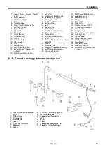
1. Presser bar lifter link
2. Shoulder screw
3. Presser bar guide bracket
4. Roller
5. Plain washer
6. Retaining ring
7. Roller shaft
8. Presser roller bracket
9. Set screw
10. Needle bar guide
11. Screws [2 pcs] (Temporarily
tighten)
12. Presser bar
13. Presser bar guide bracket
14. Oil rejector
15. Set screw (Temporarily
tighten)
16. Screws [2 pcs] (Fully tighten)
17. Presser roller bracket
18. Screw
19. Knee lifter lever
20. Shoulder screw
21. Set screw
22. Washer
23. Compression spring
24. Spring guide
25. Presser adjusting screw
26. Presser adjusting nut
27. Rubber caps [2 pcs]
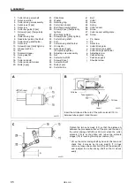
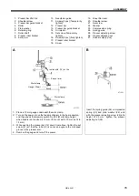
A
1
)
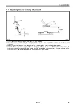
Place a 10 mm gauge underneath the work clamp.
2
)
Turn on the power, move the feed mechanism to the home position,
and then check that memory switch No. 002 (Work clamp height
when treadle is at neutral) is 10 mm. (If it is not set to 10 mm, set it to
10 mm.)
3
)
While pushing the presser bar (12) down from above, tighten the set
screw (21) so that the roller (4) is not at an angle to the V-shaped
groove in the presser arm .
4
)
Remove the gauge and turn off the power.
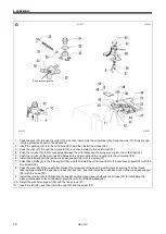
B
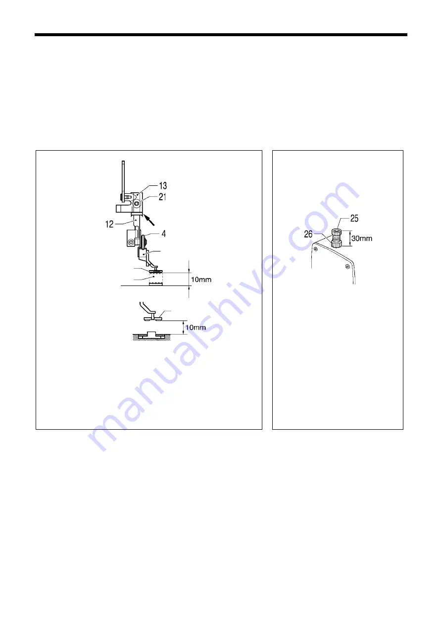
Insert the spring guide (24), compression
spring (23) and plain washer (22), and
with the presser adjusting screw (25) at a
height of 30 mm, tighten the presser
adjusting nut (26).
0717D
Work clamp
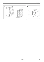
Install with (14) at the
0718D
Gauge (10mm)
Work clamp
Presser arm
Summary of Contents for HE-800B
Page 7: ...v HE 800B Oil tank accessory 4732M 4731M 4730M ...
Page 75: ...6 ASSEMBLY HE 800B 66 D E 0688D 0690D ...
Page 126: ...9 ELECTRIC MECHANISM HE 800B 117 Power PCB Cutter PCB LCD panel PCB 0831D 0768D 0769D ...
Page 133: ...9 ELECTRIC MECHANISM HE 800B 124 0851D ...
Page 134: ...9 ELECTRIC MECHANISM HE 800B 125 0852D ...
Page 135: ...9 ELECTRIC MECHANISM HE 800B 126 0853D ...
Page 177: ...MEMO 168 HE 800B ...
Page 178: ...SERVICE MANUAL 2014 Brother Industries Ltd All Rights Reserved HE 800B I3061003D 2014 03 D 1 ...

