VI
- 26
7.
STATUS MESSAGE LIST
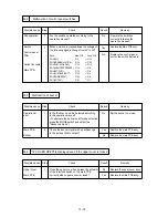
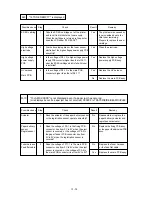
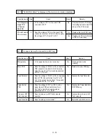
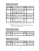
Table 6.2 Operator Call Messages
Operator Call Message
Meaning
Action
CHECK XX TRAY
12 COVER OPEN
13 JAM XXXXXX
14 NO CARTRIDGE
XX NO CASSETTE
16 TONER EMPTY
XX LOAD PAPER *****
SIZE
18 MANUAL FEED *****
SIZE
19 CHECK FONT
20 FONT REMOVAL
27 NO DX UNIT
27 NO DX TRAY
27 DX OPEN
The paper cassette (XX
is MP/T1/T2) is out of
paper.
The upper cover of the
printer is open.
Paper is jammed in the
printer. XXXXXX is
TRAYS/INSIDE/REAR/
DUPLEX.
The toner cartridge is not
installed in the printer.
The paper cassette is not
installed. XX is T1/T2.
The printer has almost
run out of toner: you may
print another 30 to 100
pages. (The ALARM
lamp lights at the same
time.)
The wrong size of paper
was loaded in the paper
cassette XX. XX is MP/
T1/T2. (The message
appears alternately to
show a particular size.)
The printer requests you
to load paper manually.
(The message appears
alternately to show a
particular size.)
An error occurred in the
optional font cartridge/
card.
The font cartridge/card
was removed while the
printer is on-line.
The duplex unit is not
installed with the printer
when the duplex printing
mode is selected.
The duplex paper guide
tray is not installed in T1
when the duplex printing
mode is selected.
The cover of the duplex
unit is open.
Load a stack of paper
into the cassette. See
M-7.
Close the cover. See
M-6.
Remove the jammed
paper from the indicated
area. See M-10.
Install a toner cartridge.
See M-8.
Install the paper cassette.
Remove the toner
cartridge, rock it several
times at 45°, and install
it again. Or replace the
toner cartridge with a new
one. See M-9.
Load the requested size
of paper in the paper
cassette, or load it on the
manual feed tray and
press the FORM FEED
switch.
Load the requested size
of paper on the multi-
purpose tray and press
the SEL switch.
Turn off the printer,
and reinstall or replace
the optional font
cartridge/card.
Turn off the printer,
install the font cartridge/
card, and turn on the
printer. The
CONTINUE switch will
allow you to temporarily
ignore this message.
Install the duplex unit
correctly.See the DX-
1200 user’s guide.
Install the duplex paper
guide tray into T1. See
the DX-1200 user’s
guide.
Close the cover. See the
DX-1200 user’s guide.
Summary of Contents for HL-1260
Page 1: ...SERVICE MANUAL MODEL HL 1260 R LASER PRINTER ...
Page 40: ...III 8 K D E F A C 2 C 3 C C 1 J B G 2 G 1 G H I Figure 3 6 Main PCB Circuit ...
Page 109: ...Appendix 3 Main PCB Circuitry Diagram 1 8 A 3 CODE NAME UK2495000 B48K158 159CIR 1 8 ...
Page 110: ...Appendix 4 Main PCB Circuitry Diagram 2 8 A 4 CODE NAME UK2495000 B48K158 159CIR 2 8 ...
Page 111: ...Appendix 5 Main PCB Circuitry Diagram 3 8 A 5 CODE NAME UK2495000 B48K158 159CIR 3 8 ...
Page 112: ...Appendix 6 Main PCB Circuitry Diagram 4 8 A 6 CODE NAME UK2495000 B48K158 159CIR 4 8 ...
Page 113: ...Appendix 7 Main PCB Circuitry Diagram 5 8 A 7 CODE NAME UK2495000 B48K158 159CIR 5 8 ...
Page 114: ...Appendix 8 Main PCB Circuitry Diagram 6 8 A 8 CODE NAME UK2495000 B48K158 159CIR 6 8 ...
Page 115: ...Appendix 9 Main PCB Circuitry Diagram 7 8 A 9 CODE NAME UK2495000 B48K158 159CIR 7 8 ...
Page 116: ...Appendix 10 Main PCB Circuitry Diagram 8 8 A 10 CODE NAME UK2495000 B48K158 159CIR 8 8 ...
Page 117: ...Appendix 11 Control Panel PCB Circuitry Diagram 1 1 A 11 CODE NAME UK2527000 B48K143CIR ...
Page 118: ...Appendix 12 Scanner LD PCB Circuitry Diagram 1 1 A 12 CODE NAME UK2674000 B48K165CIR ...
Page 119: ...SERVICE MANUAL MODEL HL 1260e 1660 R LASER PRINTER ...
Page 144: ...III 7 Figure 3 6 Main PCB Circuit A C 2 C 3 C J K B I H 1 H 2 C 1 H G G 1 G 2 F E D ...
Page 168: ...CODE UK3268000 B48K259 235CIR 1 7 NAME Appendix 3 Main PCB Circuitry Diagram 1 7 ...
Page 169: ...CODE UK3268000 B48K259 235CIR 2 7 NAME Appendix 4 Main PCB Circuitry Diagram 2 7 A 3 ...
Page 170: ...CODE UK3268000 B48K259 235CIR 3 7 NAME Appendix 5 Main PCB Circuitry Diagram 3 7 A 4 ...
Page 171: ...CODE UK3268000 B48K259 235CIR 4 7 NAME Appendix 6 Main PCB Circuitry Diagram 4 7 A 5 ...
Page 172: ...CODE UK3268000 B48K259 235CIR 5 7 NAME A 6 Appendix 7 Main PCB Circuitry Diagram 5 7 ...
Page 173: ...CODE UK3268000 B48K259 235CIR 6 7 NAME Appendix 8 Main PCB Circuitry Diagram 6 7 A 7 ...
Page 174: ...CODE UK3268000 B48K259 235CIR 7 7 NAME Appendix 9 Main PCB Circuitry Diagram 7 7 A 8 ...
Page 175: ...CODE UK3253000 B48K253CIR 1 1 NAME Appendix 11 Scanner LD PCB Circuitry Diagram 1 1 A 9 ...
Page 188: ...PARTS REFERENCE LIST MODEL HL 1260e R LASER PRINTER ...
Page 213: ...I Brother Laser Printer HL 1260e HL 1660 USER S GUIDE ...
Page 422: ...USER S GUIDE Appendix 16 PC 8 10U PC 8 D N 11U PC 850 12U PC 852 17U ...
Page 423: ...APPENDICES Appendix 17 PC 8 Turkish 9T Windows Latin1 19U Windows Latin2 9E Windows Latin5 5T ...
Page 424: ...USER S GUIDE Appendix 18 Legal 1U Ventura Math 6M Ventura Intl 13J Ventura US 14J ...
Page 425: ...APPENDICES Appendix 19 PS Math 5M PS Text 10J Math 8 8M Pi Font 15U ...
Page 426: ...USER S GUIDE Appendix 20 MS Publishing 6J Windows 3 0 9U Desktop 7J MC Text 12J ...
Page 429: ...APPENDICES Appendix 23 PC 8 PC 8 D N PC 850 PC 852 ...
Page 430: ...USER S GUIDE Appendix 24 PC 860 PC 863 PC 865 PC 8 Turkish ...
Page 431: ...APPENDICES Appendix 25 IBM Mode PC 8 PC 8 D N PC 850 PC 852 ...
Page 432: ...USER S GUIDE Appendix 26 PC 860 PC 863 PC 865 PC 8 Turkish ...
Page 433: ...APPENDICES Appendix 27 HP GL Mode ANSI ASCII 9825 CHR SET ...
Page 434: ...USER S GUIDE Appendix 28 FRENCH GERMAN SCANDINAVIAN SPANISH LATIN JIS ASCII ...
Page 435: ...APPENDICES Appendix 29 ROMAN8 EXT ISO IRV ISO SWEDISH ISO SWEDISH N ...
Page 436: ...USER S GUIDE Appendix 30 ISO NORWAY 1 ISO GERMAN ISO FRENCH ISO U K ...
Page 437: ...APPENDICES Appendix 31 ISO ITALIAN ISO SPANISH ISO PORTUGUESE ISO NORWAY 2 ...

