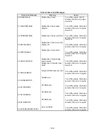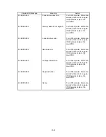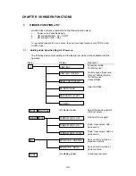
VII-2
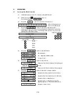
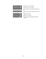
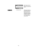
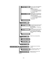
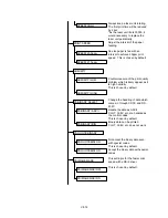
Hex dump mode
* Printer reset is need to
exit this mode.
(No display reads)
Reads the date of program /
font ROM. Press CONT to
switch program and font.
(No display reads)
Choose LCD local prompt
message.
(No display reads)
NV-RAM settings returns to
the factory default settings.
These settings are reset in
addition to the factory reset.
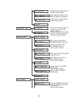
•
Interface
•
Page Protect
•
HRC
•
Panel Lock
•
Toner Density
(No display reads)
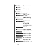
Check DRAM strictly.
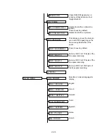
Write the data recieved
through the parallel I/F onto
flash memory modules on
the main ROM socket.
Write the data which is
stored on a PCMCIA card
onto flash memory modules
on the main ROM socket.
Write the data recieved
through the parallel I/F onto
flash memory modules on
the option ROM socket.
Write the data which is
stored on a PCMCIA card
onto flash memory modules
on the option ROM socket.
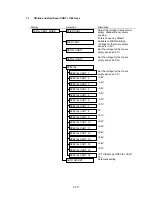
Write the data recieved
through the parallel I/F onto
patch flash memory
modules.
Write the data which is
stored on a PCMCIA card
onto patch flash memory
modules.
Write the data on the option
ROM onto flash memory
modules on the main ROM
socket.
▼
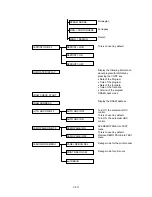
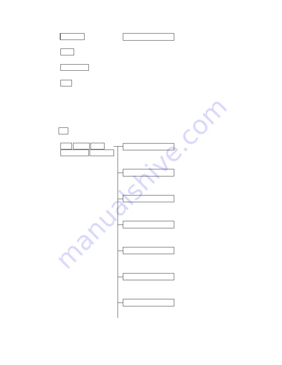
HEX DUMP MODE
PRL ---->MAIN ROM W
CARD --->MAIN ROM W
PRL ---->OPTN ROM W
CARD --->OPTN ROM W
PRL ---->PTCH ROM W
CARD --->PTCH ROM W
OPTN --->MAIN ROM W
CONTINUE
FONT
FORM FEED
SET
CONTINUE
FORM FEED
FONT
MODE
SEL
Summary of Contents for HL-2060
Page 1: ...MECHANICS ELECTRONICS SERVICE MANUAL LASER PRINTER ...
Page 41: ...III 8 A B F C D E 1 E 2 E 3 E 4 E 5 F Figure 3 7 Paper Feed Size SW PCB Circuit ...
Page 129: ...VII 16 Test for memory MEMORY DISPLAY MEMORY DEBUG MEMORY TEST exit MENU ...
Page 137: ...Appendix A 3 Main PCB Circuitry Diagram 1 7 CODE UK4058000 B512006 CIR 1 7 NAME A 3 ...
Page 138: ...Appendix A 4 Main PCB Circuitry Diagram 2 7 CODE UK4058000 B512006 CIR 2 7 NAME A 4 ...
Page 139: ...Appendix A 5 Main PCB Circuitry Diagram 3 7 CODE UK4058000 B512006 CIR 3 7 NAME A 5 ...
Page 140: ...Appendix A 6 Main PCB Circuitry Diagram 4 7 CODE UK4058000 B512006 CIR 4 7 NAME A 6 ...
Page 141: ...Appendix A 7 Main PCB Circuitry Diagram 5 7 CODE UK4058000 B512006 CIR 5 7 NAME A 7 ...
Page 142: ...Appendix A 8 Main PCB Circuitry Diagram 6 7 CODE UK4058000 B512006 CIR 6 7 NAME A 8 ...
Page 143: ...Appendix A 9 Main PCB Circuitry Diagram 7 7 CODE UK4058000 B512006 CIR 7 7 NAME A 9 ...
Page 144: ...Appendix A 10 Control Panel PCB Circuitry Diagram 1 1 CODE UK4077000 B512005 CIR NAME A 10 ...
Page 145: ...Appendix A 11 Laser LD PCB Circuitry Diagram 1 1 CODE UK3253000 B48K253 CIR NAME A 11 ...
Page 147: ...June 98 54T046NE0 HL2060 ...


