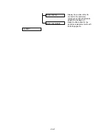
VII-6
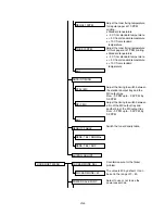
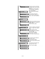
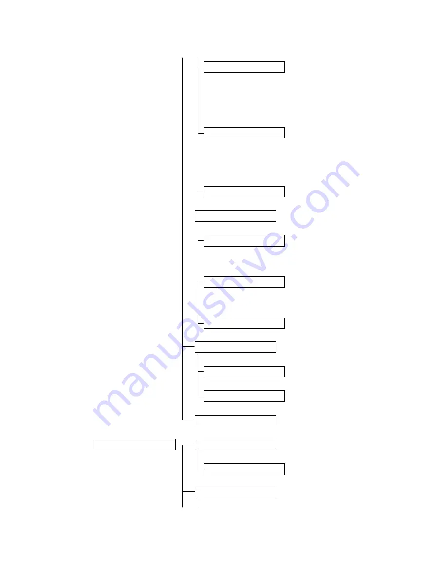
Adjust the toner fixing temperature
for ragular paper at 10 PPM
printing.
•
Standard tenperature
•
- 5 C from standard temperature
•
+ 5 C from standard temperature
•
+ 10 C from standard
temperature
Adjust the toner fixing temperature
for thick paper at 21 PPM printing.
•
Standard tenperature
•
- 5 C from standard temperature
•
+ 5 C from standard temperature
•
+ 10 C from standard
temperature
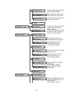
Adjust the timing to switch between
the standard output tray and the
MX output tray.
From - 0 PPM upto - 3.5 PPM, by
0.5 PPM.
Adjust the timing to switch between
a bin of the MX output tray and
another bin of the MX output tray.
From - 0 PPM upto - 3.5 PPM, by
0.5 PPM.
Switch the toner density table.
Countermeasure for the flicker
problem.
The value is 40 by default. It can
be set in the range of 0 - 63.
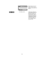
Select to use or not to use the
power save mode.
REGUL 10PPM
THICK 10PPM
exit
OUTBIN TIMING
STD<>MX
MX<>MX
exit
DENSITY TABLE
DENS. TBL =NORMAL
DENS. TBL =ADP
exit ENG ADJUST
FLICKER MODE SEL
FLICKER SET MENU
FLICKER MODE= 40
POWER SAVE FUNC
Summary of Contents for HL-2060
Page 1: ...MECHANICS ELECTRONICS SERVICE MANUAL LASER PRINTER ...
Page 41: ...III 8 A B F C D E 1 E 2 E 3 E 4 E 5 F Figure 3 7 Paper Feed Size SW PCB Circuit ...
Page 129: ...VII 16 Test for memory MEMORY DISPLAY MEMORY DEBUG MEMORY TEST exit MENU ...
Page 137: ...Appendix A 3 Main PCB Circuitry Diagram 1 7 CODE UK4058000 B512006 CIR 1 7 NAME A 3 ...
Page 138: ...Appendix A 4 Main PCB Circuitry Diagram 2 7 CODE UK4058000 B512006 CIR 2 7 NAME A 4 ...
Page 139: ...Appendix A 5 Main PCB Circuitry Diagram 3 7 CODE UK4058000 B512006 CIR 3 7 NAME A 5 ...
Page 140: ...Appendix A 6 Main PCB Circuitry Diagram 4 7 CODE UK4058000 B512006 CIR 4 7 NAME A 6 ...
Page 141: ...Appendix A 7 Main PCB Circuitry Diagram 5 7 CODE UK4058000 B512006 CIR 5 7 NAME A 7 ...
Page 142: ...Appendix A 8 Main PCB Circuitry Diagram 6 7 CODE UK4058000 B512006 CIR 6 7 NAME A 8 ...
Page 143: ...Appendix A 9 Main PCB Circuitry Diagram 7 7 CODE UK4058000 B512006 CIR 7 7 NAME A 9 ...
Page 144: ...Appendix A 10 Control Panel PCB Circuitry Diagram 1 1 CODE UK4077000 B512005 CIR NAME A 10 ...
Page 145: ...Appendix A 11 Laser LD PCB Circuitry Diagram 1 1 CODE UK3253000 B48K253 CIR NAME A 11 ...
Page 147: ...June 98 54T046NE0 HL2060 ...


