VII-15
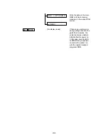
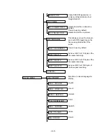
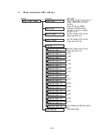
To support Windows 95 Plug &
Play.
This is chosen by default.
Not use the ranlength
decompression.
This is chosen by default.
Use the ranlength decompression
on software side.
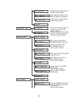
To support some MIO with a
firmware download function and
unknown timeout for restarting.
Restart MIO after the 10 min.-
timeout.
This is chosen by default.
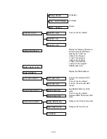
Some UNIX systems leave a
printer with MIO in open
connection and do not put it close
connection. Due to this, the data
received by the other interfaces is
not processed.
Even if a printer stays in open
connection, it is able to process
the data received by parallel and
serial I/F.This is chosen by default.
Process 2 pages data at a time.
Process 4 pages data at a time.
This is chosen by default.
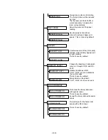
Set PJL JOB TIMEOUT (5 min.)
ON/OFF.
PJL JOB TIMEOUT is effective.
This is chosen by default.
PJL JOB TIMEOUT does not carry
out.
BOISE ID=WIN95
BOISE ID MODE
BOISE ID=IEEE
ECP RLE = OFF
ECP RLE MODE
ECP RLE = ON
MIO RESTART = OFF
MIO RESTART MODE
MIO RESTART = ON
MIO TIMEOUT MODE
MIO TIMEOUT = OFF
MIO TIMEOUT = ON
DPX MODE = SLOW
DPX MODE
DPX MODE = FAST
TIME OUT=ON
JOB TIMEOUT SEL
TIME OUT=OFF
Summary of Contents for HL-2060
Page 1: ...MECHANICS ELECTRONICS SERVICE MANUAL LASER PRINTER ...
Page 41: ...III 8 A B F C D E 1 E 2 E 3 E 4 E 5 F Figure 3 7 Paper Feed Size SW PCB Circuit ...
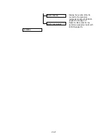
Page 129: ...VII 16 Test for memory MEMORY DISPLAY MEMORY DEBUG MEMORY TEST exit MENU ...
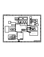
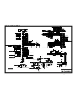
Page 137: ...Appendix A 3 Main PCB Circuitry Diagram 1 7 CODE UK4058000 B512006 CIR 1 7 NAME A 3 ...
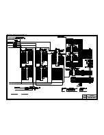
Page 138: ...Appendix A 4 Main PCB Circuitry Diagram 2 7 CODE UK4058000 B512006 CIR 2 7 NAME A 4 ...
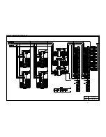
Page 139: ...Appendix A 5 Main PCB Circuitry Diagram 3 7 CODE UK4058000 B512006 CIR 3 7 NAME A 5 ...
Page 140: ...Appendix A 6 Main PCB Circuitry Diagram 4 7 CODE UK4058000 B512006 CIR 4 7 NAME A 6 ...
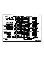
Page 141: ...Appendix A 7 Main PCB Circuitry Diagram 5 7 CODE UK4058000 B512006 CIR 5 7 NAME A 7 ...
Page 142: ...Appendix A 8 Main PCB Circuitry Diagram 6 7 CODE UK4058000 B512006 CIR 6 7 NAME A 8 ...
Page 143: ...Appendix A 9 Main PCB Circuitry Diagram 7 7 CODE UK4058000 B512006 CIR 7 7 NAME A 9 ...
Page 144: ...Appendix A 10 Control Panel PCB Circuitry Diagram 1 1 CODE UK4077000 B512005 CIR NAME A 10 ...
Page 145: ...Appendix A 11 Laser LD PCB Circuitry Diagram 1 1 CODE UK3253000 B48K253 CIR NAME A 11 ...
Page 147: ...June 98 54T046NE0 HL2060 ...

