VII-19
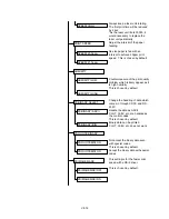
Carry out the page protect if it is
turned OFF.
This is chosen by default.
Reset a printer with ESC E.
This is chosen by default.
Carry out form feed with ESC E.
This is chosen by default.
Not eject paper if both the 1
st
and 2
nd
faces are blank.
This is chosen by default.
When the total memory is 2MB, 300
dpi is automatically selected in PS for
less memory full.
Use 300 dpi only in PS.
This setting delays paper jam error
detection.
This is chosen by default.
This is chosen by default.
1 page is fixed for the copy page
number.
Settings made on the panel are
reset job by job.
This is chosen by default.
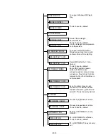
Turn ON USB function.
This is chosen by default.
Turn OFF USB function.
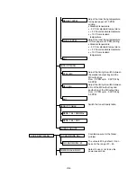
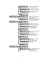
PRO.OFF=AUTO
PRO.OFF=NORMAL
PROTECT OFF MODE
HP ESC E=RESET
HP ESC E =F/F
HP ESC E COMMAND
DPX FF SUP. =NORMAL
DPX FF SUP. =SPEC.
DPX FF SUP. MODE
PS300RESO =IF 2M
PS300RESO =NO
PS300RESO
PS300RESO =FORCE
JAM CHECK=TIGHT
JAM CHECK=LOOSE
JAM CHECK LEVEL
COPY PAGES=ON
COPY PAGES=OFF
COPY PAGES
RESET=JOB
RESET=NORMAL
PANEL RESET MODE
USB=ENABLE
USB=DISABLE
USB SETTING
Summary of Contents for HL-2060
Page 1: ...MECHANICS ELECTRONICS SERVICE MANUAL LASER PRINTER ...
Page 41: ...III 8 A B F C D E 1 E 2 E 3 E 4 E 5 F Figure 3 7 Paper Feed Size SW PCB Circuit ...
Page 129: ...VII 16 Test for memory MEMORY DISPLAY MEMORY DEBUG MEMORY TEST exit MENU ...
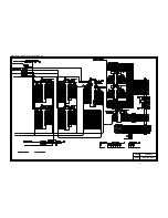
Page 137: ...Appendix A 3 Main PCB Circuitry Diagram 1 7 CODE UK4058000 B512006 CIR 1 7 NAME A 3 ...
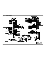
Page 138: ...Appendix A 4 Main PCB Circuitry Diagram 2 7 CODE UK4058000 B512006 CIR 2 7 NAME A 4 ...
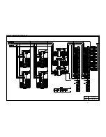
Page 139: ...Appendix A 5 Main PCB Circuitry Diagram 3 7 CODE UK4058000 B512006 CIR 3 7 NAME A 5 ...
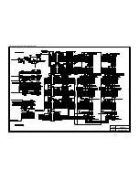
Page 140: ...Appendix A 6 Main PCB Circuitry Diagram 4 7 CODE UK4058000 B512006 CIR 4 7 NAME A 6 ...
Page 141: ...Appendix A 7 Main PCB Circuitry Diagram 5 7 CODE UK4058000 B512006 CIR 5 7 NAME A 7 ...
Page 142: ...Appendix A 8 Main PCB Circuitry Diagram 6 7 CODE UK4058000 B512006 CIR 6 7 NAME A 8 ...
Page 143: ...Appendix A 9 Main PCB Circuitry Diagram 7 7 CODE UK4058000 B512006 CIR 7 7 NAME A 9 ...
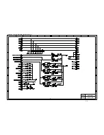
Page 144: ...Appendix A 10 Control Panel PCB Circuitry Diagram 1 1 CODE UK4077000 B512005 CIR NAME A 10 ...
Page 145: ...Appendix A 11 Laser LD PCB Circuitry Diagram 1 1 CODE UK3253000 B48K253 CIR NAME A 11 ...
Page 147: ...June 98 54T046NE0 HL2060 ...


