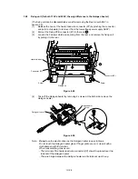
IV-10
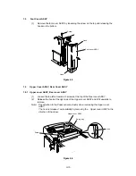
(3)
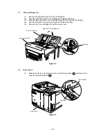
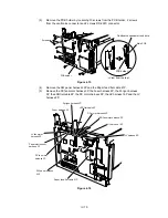
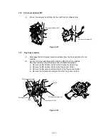
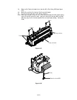
Remove the PCB holder by loosening 10 screws from the PCB holder, 2 screws
from the centronics connector and 2 screws RS-232C connector.
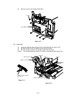
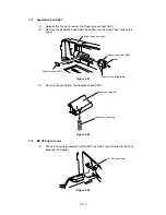
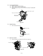
Figure 4.15
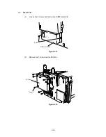
(4)
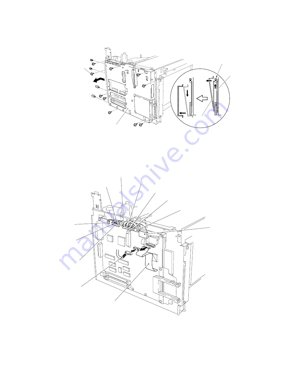
Remove the SW panel harness 22P and the Paper feed flat cable 21P.
(5)
Remove the DC fan motor harness 3P, the Fuser harness 4P, the Porigon harness
5P, the LSR flat cable 6P, the DC motor harness 5P, the HV harness 16P and the LV
harness 8P.
Figure 4.16
PCB holder
Screws
Main PCB
PCB holder
< View from the top >
Centronics connector lock wire
Paper feed flat cable 21P
Porigon harness 5P
HV harness 16P
DC motor harness 5P
LV harness 8P
SW panel harness
22P
Fuser harness 4P
LSR flat cable 6P
LSR fan motor harness 2P
LV fan motor
harness 2P
Paper eject sensor
harness 3P
DC fan motor
harness 3P
Summary of Contents for HL-2060
Page 1: ...MECHANICS ELECTRONICS SERVICE MANUAL LASER PRINTER ...
Page 41: ...III 8 A B F C D E 1 E 2 E 3 E 4 E 5 F Figure 3 7 Paper Feed Size SW PCB Circuit ...
Page 129: ...VII 16 Test for memory MEMORY DISPLAY MEMORY DEBUG MEMORY TEST exit MENU ...
Page 137: ...Appendix A 3 Main PCB Circuitry Diagram 1 7 CODE UK4058000 B512006 CIR 1 7 NAME A 3 ...
Page 138: ...Appendix A 4 Main PCB Circuitry Diagram 2 7 CODE UK4058000 B512006 CIR 2 7 NAME A 4 ...
Page 139: ...Appendix A 5 Main PCB Circuitry Diagram 3 7 CODE UK4058000 B512006 CIR 3 7 NAME A 5 ...
Page 140: ...Appendix A 6 Main PCB Circuitry Diagram 4 7 CODE UK4058000 B512006 CIR 4 7 NAME A 6 ...
Page 141: ...Appendix A 7 Main PCB Circuitry Diagram 5 7 CODE UK4058000 B512006 CIR 5 7 NAME A 7 ...
Page 142: ...Appendix A 8 Main PCB Circuitry Diagram 6 7 CODE UK4058000 B512006 CIR 6 7 NAME A 8 ...
Page 143: ...Appendix A 9 Main PCB Circuitry Diagram 7 7 CODE UK4058000 B512006 CIR 7 7 NAME A 9 ...
Page 144: ...Appendix A 10 Control Panel PCB Circuitry Diagram 1 1 CODE UK4077000 B512005 CIR NAME A 10 ...
Page 145: ...Appendix A 11 Laser LD PCB Circuitry Diagram 1 1 CODE UK3253000 B48K253 CIR NAME A 11 ...
Page 147: ...June 98 54T046NE0 HL2060 ...

