VI-13
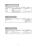
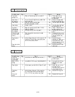
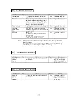
M-7 "14 NO CARTRIDGE" is displayed
Possible cause
Step
Check
Result
Remedy
EP-ED HC
cartridge
1
Is an EP-ED HC cartridge installed correctly?
No
Install the EP-ED HC
cartridge correctly.
Transfer unit
electrode
2
Is the electrode of the transfer unit dirty?
Yes
Clean the electrode of the
transfer unit.
High-voltage
power supply
PCB
3
Is the voltage of P4-13 in the high-voltage
power supply PCB connector higher than that
of P4-11 over 2.5V?
Yes
Replace the high-voltage
power supply PCB assy.
HV harness
4
Is the voltage of P6-13 in the main PCB
connector higher than that of P6-11 over 2.5V?
Yes
Replace the HV harness.
Main PCB
No
Replace the main PCB
assy.
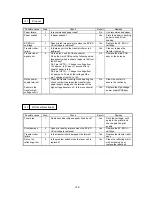
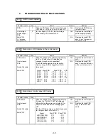
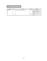
M-8 "16 TONER EMPTY" is displayed
Possible cause
Step
Check
Result
Remedy
EP-ED HC
cartridge
1
Take the EP-ED HC cartridge out of the printer
and rock it to distribute the toner evenly.
When the cartridge is returned to the printer,
does the LCD show "00 READY" ?
Yes
The problem was caused
by toner one-sided due to
too little toner remaining.
Prepare to replace the
new cartridge.
High-voltage
electrode
2
Are the developing bias or the toner sensor
electrode of the high-voltage power supply
PCB assy dirty?
Yes
Clean the electrode.
High-voltage
power supply
PCB
3
Is the voltage of P2-13 in high-voltage power
supply PCB connector higher than that of
P2-11, when the EP-ED HC cartridge which is
full with toner is installed?
Yes
Replace the high-voltage
power supply PCB assy.
HV harness
4
Is the voltage of P6-13 in the main PCB
connector higher than that of P6-11?
Yes
Replace the HV harness.
Main PCB
No
Replace the main PCB
assy.
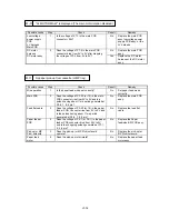
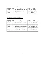
M-9 "13 JAM XXXXXX" is not displayed even if a paper jam has occurred
(or is displayed even if a paper jam has not occurred) XXXXXX is TRAYS/INSIDE/REAR/DUPLEX.
Possible cause
Step
Check
Result
Remedy
Actuator
1
Does the actuator of the paper delivery sensor
or the registration sensor operate smoothly?
No
Reassemble or replace
the paper delivery
actuator and regist sensor
actuator.
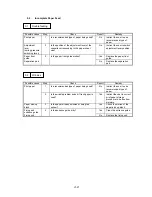
Paper delivery
sensor
Regist sensor
2
Does the voltage of P2-1 in the fixing PCB
connector rise from 0V to 5V when the eject
sensor is covered, or the voltage of P5-5 in the
paper feeder PCB connector rise from 0V to
5V when the registration sensor is covered?
No
Replace the fixing PCB
assy or the paper
feed/size-sw PCB assy.
Fuser harness
Feed flat cable
3
Does the voltage of P11-1 in the main PCB
connector rise from 0V to 5V when the eject
No
Replace the fuser harness
or the feed flat cable.
sensor is covered, or the voltage of P3-5 in the
main PCB connector rise from 0V to 5V?
Yes
Replace the main PCB
assy.
Summary of Contents for HL-2060
Page 1: ...MECHANICS ELECTRONICS SERVICE MANUAL LASER PRINTER ...
Page 41: ...III 8 A B F C D E 1 E 2 E 3 E 4 E 5 F Figure 3 7 Paper Feed Size SW PCB Circuit ...
Page 129: ...VII 16 Test for memory MEMORY DISPLAY MEMORY DEBUG MEMORY TEST exit MENU ...
Page 137: ...Appendix A 3 Main PCB Circuitry Diagram 1 7 CODE UK4058000 B512006 CIR 1 7 NAME A 3 ...
Page 138: ...Appendix A 4 Main PCB Circuitry Diagram 2 7 CODE UK4058000 B512006 CIR 2 7 NAME A 4 ...
Page 139: ...Appendix A 5 Main PCB Circuitry Diagram 3 7 CODE UK4058000 B512006 CIR 3 7 NAME A 5 ...
Page 140: ...Appendix A 6 Main PCB Circuitry Diagram 4 7 CODE UK4058000 B512006 CIR 4 7 NAME A 6 ...
Page 141: ...Appendix A 7 Main PCB Circuitry Diagram 5 7 CODE UK4058000 B512006 CIR 5 7 NAME A 7 ...
Page 142: ...Appendix A 8 Main PCB Circuitry Diagram 6 7 CODE UK4058000 B512006 CIR 6 7 NAME A 8 ...
Page 143: ...Appendix A 9 Main PCB Circuitry Diagram 7 7 CODE UK4058000 B512006 CIR 7 7 NAME A 9 ...
Page 144: ...Appendix A 10 Control Panel PCB Circuitry Diagram 1 1 CODE UK4077000 B512005 CIR NAME A 10 ...
Page 145: ...Appendix A 11 Laser LD PCB Circuitry Diagram 1 1 CODE UK3253000 B48K253 CIR NAME A 11 ...
Page 147: ...June 98 54T046NE0 HL2060 ...


