CHAPTER 4 STRUCTURE OF SYSTEM COMPONENTS
4-62
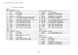
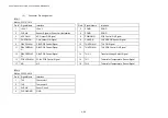
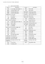
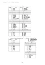
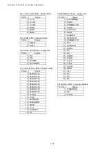
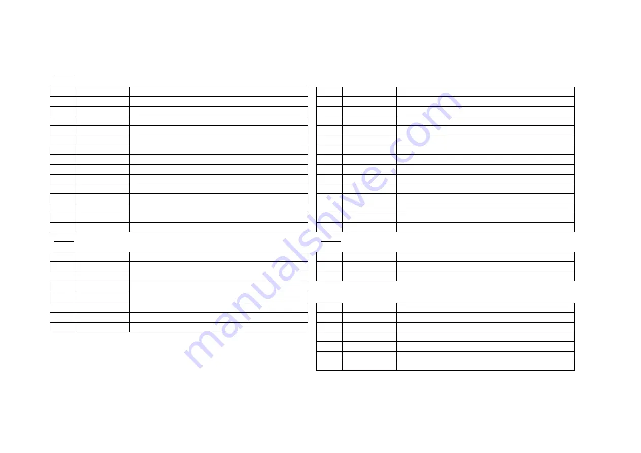
(3)
Connector Pin Assignment
ACN1
MoLex: 53313-2815
Pin # Signal Name
Interface
Pin # Signal Name
Interface
1
+5V-1
+5V-1 Output
2
DCOFF2-P
+5V-2D OFF Signal
3
+5V-1
+5V-1 Output
4
SGND
Signal Ground (+5V type ground)
5
+5V-D
+5V-D Output
6
SGND
Signal Ground (+5V type ground)
7
+5V-D
+5V-D Output
8
SGND
Signal Ground (+5V type ground)
9
ACSYNC-N
AC Zero-Cross Signal (Open Collector Output)
10
SGND
Signal Ground (+5V type ground)
11
+24V
+24V Output Corresponding to Door Switch
12
DCOFF1-P
OFF Signal (Pull-up required)
13
+5V-1R
+5V through the relay when +24V-1 is shut down.
14
ACOFF-P
AC Forced Shut-down Signal (Pull-up required)
15
HON-N
Heater On Signal (Pull-up required)
16
TESTI2
Terminal for Dielectric Strength Test
17
+24V-1
+24V Output through Door Switch
18
TESTO2
Terminal for Dielectric Strength Test
19
+24V-1
+24V Output through Door Switch
20
TESTI1
Terminal for Dielectric Strength Test
21
+24V-1
+24V Output through Door Switch
22
TESTO1
Terminal for Dielectric Strength Test
23
+24V-1
+24V Output through Door Switch
24
PGND
Power Ground (+24V type ground)
25
PGND
Power Ground (+24V type ground)
26
PGND
Power Ground (+24V type ground)
27
PGND
Power Ground (+24V type ground)
28
PGND
Power Ground (+24V type ground)
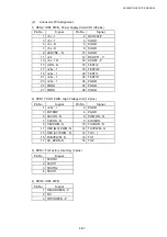
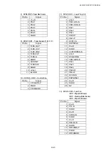
ACN1
ACN1
MoLex: 53324-0710
MoLex: 5277-02A
Pin # Signal Name
Interface
Pin # Signal Name
Interface
1
+5V-1
+5V-1 Output
1
DSW-O
+24V Output through Door switch
2
+5V-D
+5V-D Output
2
DSW-I
+24V Output through Door switch
3
SGND
Signal Ground (+5V type ground)
ACN3
4 +24V-2
+24V-2
Output
MoLex: 5566-06A
5
+24V-2
+24V-2 Output
Pin # Signal Name
Interface
6
PGND
Power Ground (+24V type ground)
1
+5V-2
+5V-2 Output
7
PGND
Power Ground (+24V type ground)
2
+5V-2D
+5V-2D Output
3 +5V-2D
+5V-2D
Output
4
SGND
Signal Ground (+5V type ground)
5
SGND
Signal Ground (+5V type ground)
6
SGND
Signal Ground (+5V type ground)
Summary of Contents for HL-3450CN Series
Page 15: ...HL 3450CN SERVICE MANUAL xiii 3 Rating Label For US For Europe 4 Operation Label 5 Jam Label ...
Page 17: ...HL 3450CN SERVICE MANUAL CHAPTER 1 PRODUCT OUTLINE ...
Page 27: ...HL 3450CN SERVICE MANUAL CHAPTER 2 SPECIFICATIONS ...
Page 39: ...CHAPTER 3 INSTALLATION ...
Page 54: ...HL 3450CN SERVICE MANUAL CHAPTER 4 STRUCTURE OF SYSTEM COMPONENTS ...
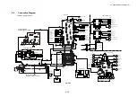
Page 104: ...HL 3450CN SERVICE MANUAL 4 51 Main PCB Circuit Diagram 1 8 CODE B512137CIR 1 8 LJ8907001 NAME ...
Page 106: ...HL 3450CN SERVICE MANUAL 4 53 Main PCB Circuit Diagram 3 8 CODE B512137CIR 3 8 LJ8907001 NAME ...
Page 108: ...HL 3450CN SERVICE MANUAL 4 55 Main PCB Circuit Diagram 5 8 CODE B512137CIR 5 8 LJ8907001 NAME ...
Page 110: ...HL 3450CN SERVICE MANUAL 4 57 Main PCB Circuit Diagram 7 8 CODE B512137CIR 7 8 LJ8907001 NAME ...
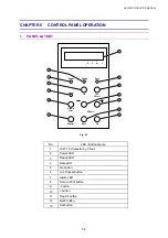
Page 126: ...HL 3450CN SERVICE MANUAL CHAPTER 5 CONTROL PANEL OPERATION ...
Page 173: ...HL 3450CN SERVICE MANUAL CHAPTER 6 PERIODIC MAINTENANCE ...
Page 208: ...CHAPTER 7 DISASSEMBLY RE ASSEMBLY ...
Page 264: ...HL 3450CN SERVICE MANUAL CHAPTER 8 TROUBLESHOOTING ...
Page 310: ...HL 3450CN SERVICE MANUAL 8 47 5 IMAGE FAILURE 1 2 3 4 5 6 7 8 9 a 9 b 10 11 12 13 14 ...
Page 311: ...CHAPTER 8 TROUBLESHOOTING 8 48 15 a 15 b 16 17 18 19 20 21 22 23 24 25 26 27 28 244m m 29 ...


