CHAPTER 4 STRUCTURE OF SYSTEM COMPONENTS
4-66
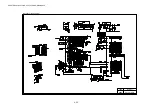
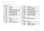
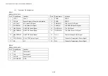
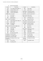
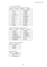
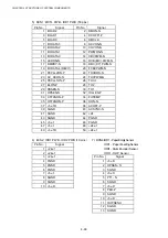
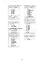
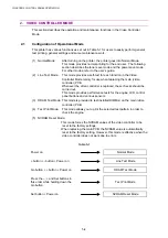
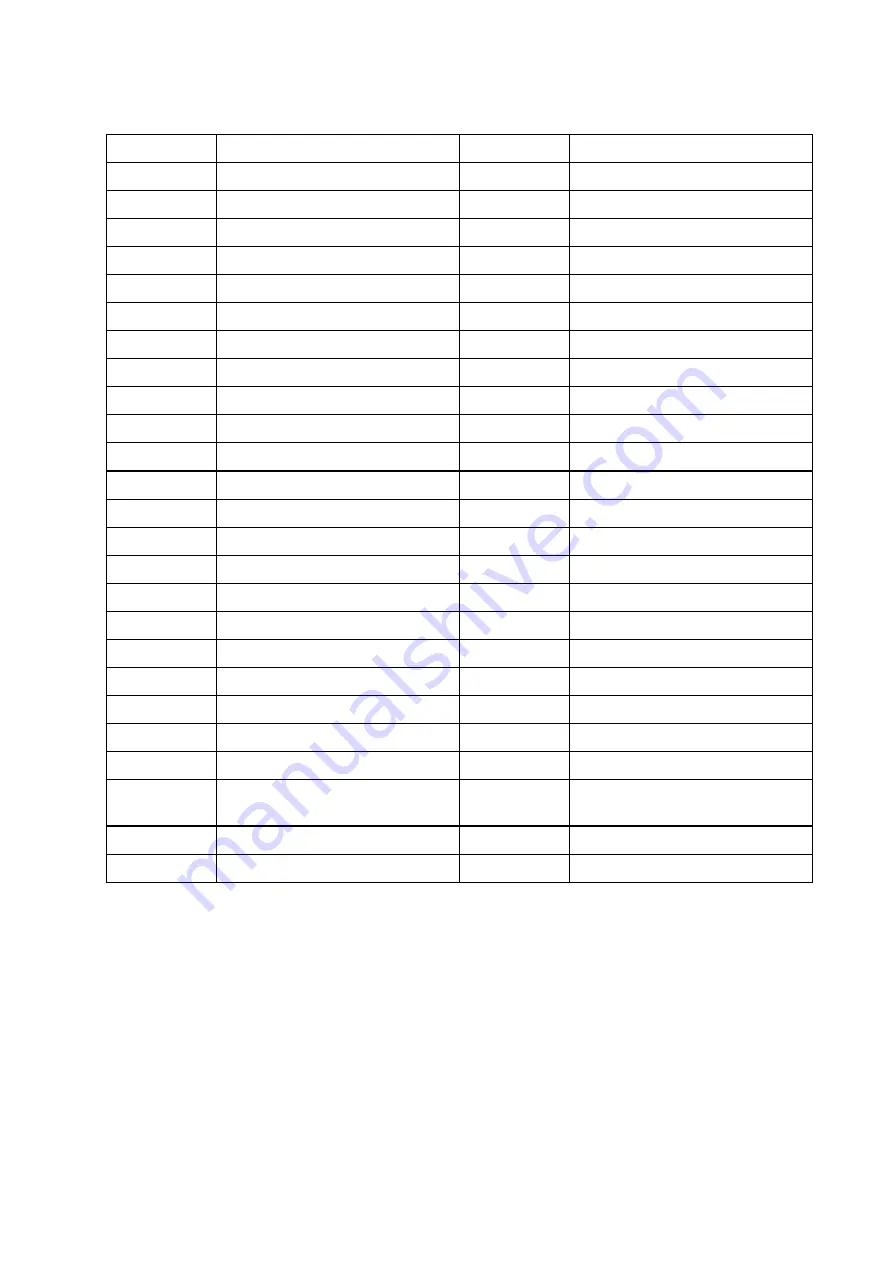
(1)
Symbol and Parts Name
Symbol
Parts Name
Symbol
Parts Name
LVPS
Low-voltage power supply unit
IOD1
IOD1 PWB
DSW1
Interlock switch (Front)
OHP
OHP sensor
DSW2
Interlock switch (Top)
PEU (PS3)
Paper empty sensor
DSW3
Interlock switch (Back)
PT1 (PS1)
Paper feeding sensor
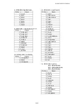
FUSER Unit
Fusing unit
EN (PS4)
Drum encoder sensor
TH
Thermistor
Erase Lamp
Erase lamp
HR
Heat roller
TDP / TTR
Toner sensor
BR
Back-up roller
TNK
Toner key sensor
TFU1 / TFU2
Thermal fuse
PSU
Paper size sensor
HVU
High-voltage power supply unit
PFUL (PS6)
Paper full sensor
MCTL
MCTL PWB
CSR (PS5)
Cleaning roller sensor
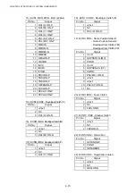
PANEL
Panel PWB
PT2 (PS2)
Paper exit sensor
LCD
LCD PWB
DPJ
Drum jam sensor
Scanner Unit
Scanner Unit (Optical unit)
OIL
Oil sensor
SCM
Scanner motor
BPS
Belt sensor
PDU
PDL PCB
TBLE / TBFL
Waste toner sensor
LDU
LDU PCB
IOD2
IOD2 PWB
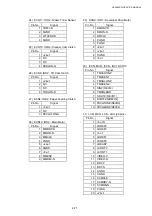
MM
Main motor
IOD3
IOD3 PWB
DM
Developer drive motor
FBCM
Cleaning cam clutch
FUFAN (EX)
fuser fan motor
TRCM
TR cam clutch
CTFAN (PS)
Control fan motor
LFU
Lower tray unit
OZFAN (OZ)
Ozone fan motor
PCLU
Paper feeding clutch
DVLK/DVLY/
DVLM/DVLC
Developer clutch (K.Y.M.C)
PSL(MC) /
PSL (KY)
Developer cam clutch
FUCL
Fuser clutch
RECL
Registration clutch
FBCL Cleaning
clutch
Summary of Contents for HL-3450CN Series
Page 15: ...HL 3450CN SERVICE MANUAL xiii 3 Rating Label For US For Europe 4 Operation Label 5 Jam Label ...
Page 17: ...HL 3450CN SERVICE MANUAL CHAPTER 1 PRODUCT OUTLINE ...
Page 27: ...HL 3450CN SERVICE MANUAL CHAPTER 2 SPECIFICATIONS ...
Page 39: ...CHAPTER 3 INSTALLATION ...
Page 54: ...HL 3450CN SERVICE MANUAL CHAPTER 4 STRUCTURE OF SYSTEM COMPONENTS ...
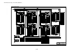
Page 104: ...HL 3450CN SERVICE MANUAL 4 51 Main PCB Circuit Diagram 1 8 CODE B512137CIR 1 8 LJ8907001 NAME ...
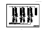
Page 106: ...HL 3450CN SERVICE MANUAL 4 53 Main PCB Circuit Diagram 3 8 CODE B512137CIR 3 8 LJ8907001 NAME ...
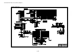
Page 108: ...HL 3450CN SERVICE MANUAL 4 55 Main PCB Circuit Diagram 5 8 CODE B512137CIR 5 8 LJ8907001 NAME ...
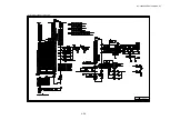
Page 110: ...HL 3450CN SERVICE MANUAL 4 57 Main PCB Circuit Diagram 7 8 CODE B512137CIR 7 8 LJ8907001 NAME ...
Page 126: ...HL 3450CN SERVICE MANUAL CHAPTER 5 CONTROL PANEL OPERATION ...
Page 173: ...HL 3450CN SERVICE MANUAL CHAPTER 6 PERIODIC MAINTENANCE ...
Page 208: ...CHAPTER 7 DISASSEMBLY RE ASSEMBLY ...
Page 264: ...HL 3450CN SERVICE MANUAL CHAPTER 8 TROUBLESHOOTING ...
Page 310: ...HL 3450CN SERVICE MANUAL 8 47 5 IMAGE FAILURE 1 2 3 4 5 6 7 8 9 a 9 b 10 11 12 13 14 ...
Page 311: ...CHAPTER 8 TROUBLESHOOTING 8 48 15 a 15 b 16 17 18 19 20 21 22 23 24 25 26 27 28 244m m 29 ...


