HL-3450CN SERVICE MANUAL
5-9
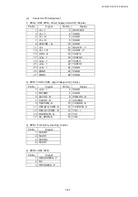
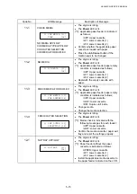
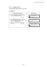
2.3
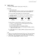
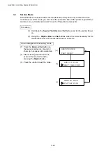
DRAM Test Mode
This mode tests DIMMs installed on the main (video controller) PCB.
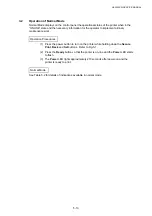
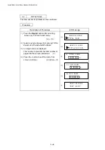
<Procedure>
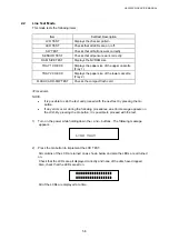
1) To start the test program:
While holding down the Go button and + button, turn on the power. “DRAM CHECK
START” will be displayed. Press the Job Cancel button to start the DRAM check.
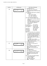
2) The LCD will display “START DRAM TEST”, and the Data LED blinks.
3) On satisfactory completion of all the RAM tests, the LCD will display: “DRAM OK!!”,
and the Alarm LED is on.
4) If any DRAM error has occurred, the LCD will display a fail message as follows;
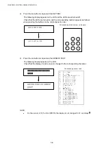
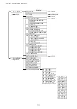
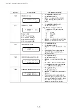
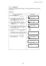
5) Enter the hidden menu mode as follows to confirm the current memory map;
i) Press the -, + and Set buttons in this order while holding down the Go button.
ii) The LCD will display “HIDDEN PANEL”
iii) Select the “DRAM ADDRESS” menu using the scroll buttons.
iv) Whenever the Set button is pressed, the LCD will display the DRAM error address
on Slot 1, Slot 2, and Slot 3 in turn.
6) If a DIMM DRAM has an error, replace the DIMM corresponding to the above memory
map information.
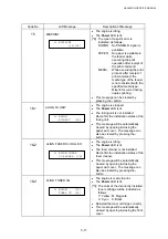
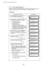
Note:
x
There may be a case where the above sequence does not work correctly due to complete
RAM failure, or in faulty assembly such as a solder bridge or ineffective soldering etc.
x
“PRINT CHECK” may be displayed when exiting from the Test mode. It will disappear in
20 or 30 seconds, displaying “READY” on the LCD. It is not a fault.
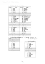
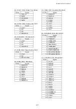
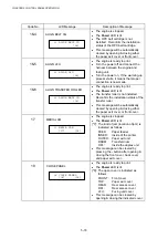
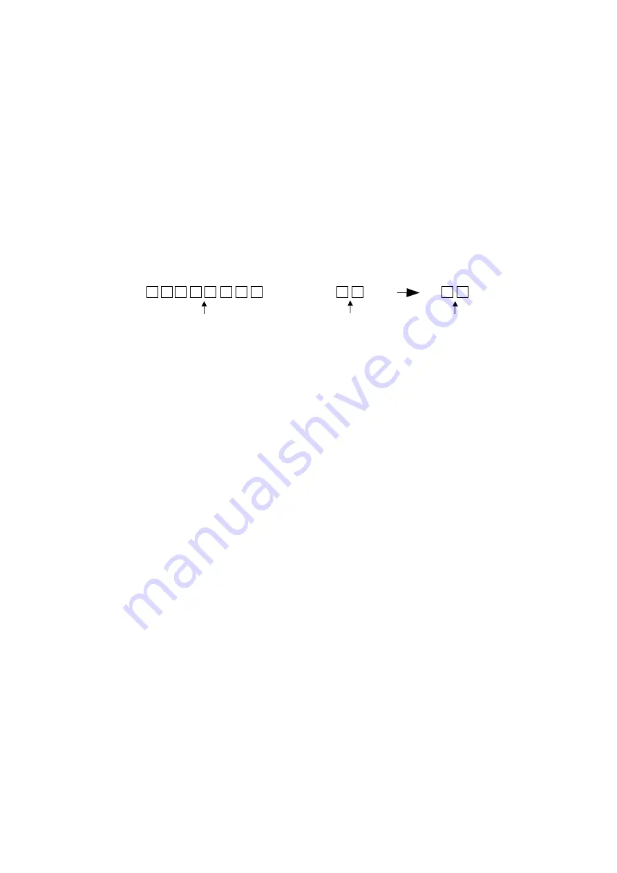
RAM Address
WRITE data
READ data
Summary of Contents for HL-3450CN Series
Page 15: ...HL 3450CN SERVICE MANUAL xiii 3 Rating Label For US For Europe 4 Operation Label 5 Jam Label ...
Page 17: ...HL 3450CN SERVICE MANUAL CHAPTER 1 PRODUCT OUTLINE ...
Page 27: ...HL 3450CN SERVICE MANUAL CHAPTER 2 SPECIFICATIONS ...
Page 39: ...CHAPTER 3 INSTALLATION ...
Page 54: ...HL 3450CN SERVICE MANUAL CHAPTER 4 STRUCTURE OF SYSTEM COMPONENTS ...
Page 104: ...HL 3450CN SERVICE MANUAL 4 51 Main PCB Circuit Diagram 1 8 CODE B512137CIR 1 8 LJ8907001 NAME ...
Page 106: ...HL 3450CN SERVICE MANUAL 4 53 Main PCB Circuit Diagram 3 8 CODE B512137CIR 3 8 LJ8907001 NAME ...
Page 108: ...HL 3450CN SERVICE MANUAL 4 55 Main PCB Circuit Diagram 5 8 CODE B512137CIR 5 8 LJ8907001 NAME ...
Page 110: ...HL 3450CN SERVICE MANUAL 4 57 Main PCB Circuit Diagram 7 8 CODE B512137CIR 7 8 LJ8907001 NAME ...
Page 126: ...HL 3450CN SERVICE MANUAL CHAPTER 5 CONTROL PANEL OPERATION ...
Page 173: ...HL 3450CN SERVICE MANUAL CHAPTER 6 PERIODIC MAINTENANCE ...
Page 208: ...CHAPTER 7 DISASSEMBLY RE ASSEMBLY ...
Page 264: ...HL 3450CN SERVICE MANUAL CHAPTER 8 TROUBLESHOOTING ...
Page 310: ...HL 3450CN SERVICE MANUAL 8 47 5 IMAGE FAILURE 1 2 3 4 5 6 7 8 9 a 9 b 10 11 12 13 14 ...
Page 311: ...CHAPTER 8 TROUBLESHOOTING 8 48 15 a 15 b 16 17 18 19 20 21 22 23 24 25 26 27 28 244m m 29 ...


