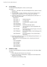
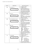
CHAPTER 5 CONTROL PANEL OPERATION
5-22
32
NEXT CARE INFORMATION
Information relating to the replacement timing of periodical replacement parts can be
obtained. This is the life for each of the components in images or pages.
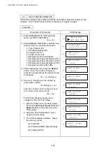
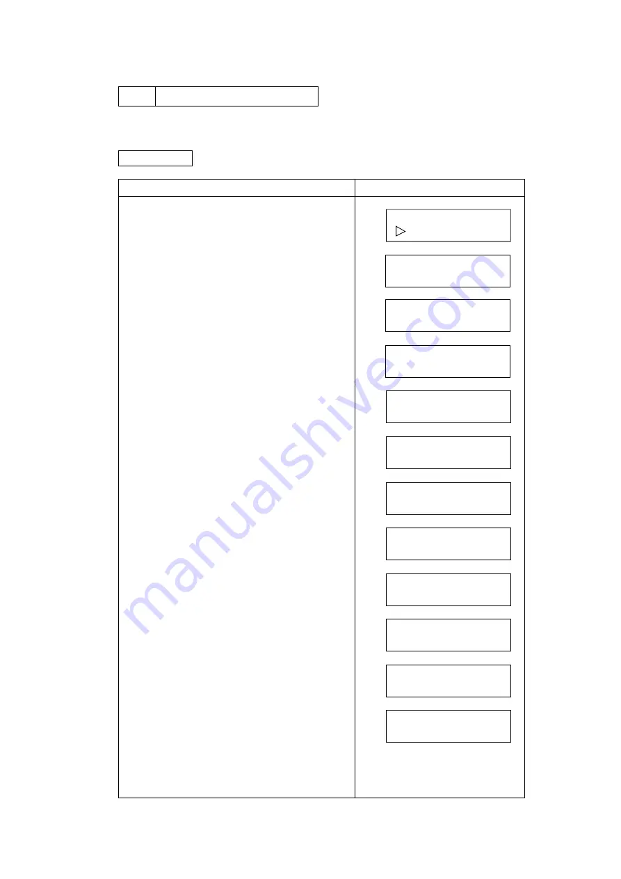
Procedure
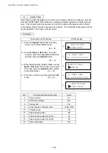
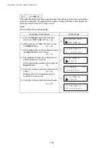
Description of Procedures
LCD Message
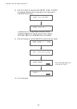
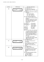
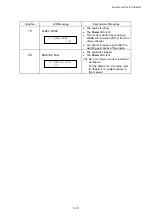
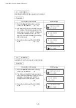
1) Press the Reprint button after selecting
Screen (a) “NEXT CARE INFO”.
(a)
o
(b)
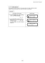
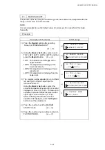
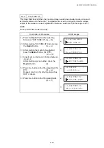
2) Using the Back or Set button, select the care
code for which you need the information.
2: Fuser Cleaner (FC)
7: OPC Belt Cartridge (BL)
8: Fusing Unit (FU) *
9: Transfer Drum (TD)
10: Replacement Kit 240K (240K)
13: Replacement Paper Feeding Kit (PF1)
14: Replacement Paper Feeding Kit (PF2)
15: Replacement Paper Feeding Kit (PF3)
16: Replacement Kit 120K (120K)
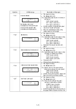
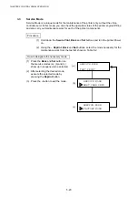
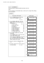
3) After selecting the code, press the Reprint
button. Then, the number of images or
printouts corresponding to the selected code
is displayed.
(b)
o
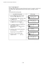
(c) through (l)
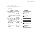
4) Screen (c) through (l) can be cleared by
pressing the - button.
(c) through (l)
o
(b)
Press
the
- button one more time at screen
(b) to return to the service mode.
(b)
o
(a)
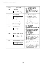
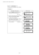
* The Oil Pad change message can be
changed to ON or OFF as follows:
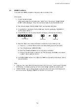
1. Enter the hidden menu mode as follows:
Press the Job Cancel, Secure Print and
Reprint buttons at the same time in the
off-line status.
2. Select the “OIL PAD SELECT” menu
using the scroll buttons.
3. The LCD will display as follows. Select
the mode you need.
OIL PAD=OFF
OIL PAD=LCD/WEB (default setting)
OIL PAD=ALLDISP
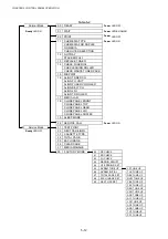
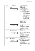
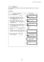
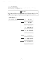
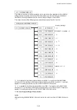
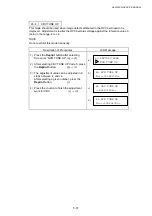
SERVICE MODE
NEXT CARE INFO
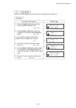
32 NEXT CARE
1,2,3,4,5,6,7,8,9,10
* 12 * * * 16
NEXT FC ROLL
018000P
NEXT BL UNIT
12000P
NEXT FU UNIT
a)
b)
c)
d)
e)
f)
100000P
NEXT TR DRUM
600000P
g)
NEXT TR DRUM
599943P
NEXT 240K KIT
24000P
NEXT PICK ROL
h)
i)
j)
120000P
NEXT PICK LF1
120000P
k)
NEXT PICK LF2
120000P
l)
NEXT P. DSCHRG
120000P
Summary of Contents for HL-3450CN Series
Page 15: ...HL 3450CN SERVICE MANUAL xiii 3 Rating Label For US For Europe 4 Operation Label 5 Jam Label ...
Page 17: ...HL 3450CN SERVICE MANUAL CHAPTER 1 PRODUCT OUTLINE ...
Page 27: ...HL 3450CN SERVICE MANUAL CHAPTER 2 SPECIFICATIONS ...
Page 39: ...CHAPTER 3 INSTALLATION ...
Page 54: ...HL 3450CN SERVICE MANUAL CHAPTER 4 STRUCTURE OF SYSTEM COMPONENTS ...
Page 104: ...HL 3450CN SERVICE MANUAL 4 51 Main PCB Circuit Diagram 1 8 CODE B512137CIR 1 8 LJ8907001 NAME ...
Page 106: ...HL 3450CN SERVICE MANUAL 4 53 Main PCB Circuit Diagram 3 8 CODE B512137CIR 3 8 LJ8907001 NAME ...
Page 108: ...HL 3450CN SERVICE MANUAL 4 55 Main PCB Circuit Diagram 5 8 CODE B512137CIR 5 8 LJ8907001 NAME ...
Page 110: ...HL 3450CN SERVICE MANUAL 4 57 Main PCB Circuit Diagram 7 8 CODE B512137CIR 7 8 LJ8907001 NAME ...
Page 126: ...HL 3450CN SERVICE MANUAL CHAPTER 5 CONTROL PANEL OPERATION ...
Page 173: ...HL 3450CN SERVICE MANUAL CHAPTER 6 PERIODIC MAINTENANCE ...
Page 208: ...CHAPTER 7 DISASSEMBLY RE ASSEMBLY ...
Page 264: ...HL 3450CN SERVICE MANUAL CHAPTER 8 TROUBLESHOOTING ...
Page 310: ...HL 3450CN SERVICE MANUAL 8 47 5 IMAGE FAILURE 1 2 3 4 5 6 7 8 9 a 9 b 10 11 12 13 14 ...
Page 311: ...CHAPTER 8 TROUBLESHOOTING 8 48 15 a 15 b 16 17 18 19 20 21 22 23 24 25 26 27 28 244m m 29 ...