HL-3450CN SERVICE MANUAL
5-31
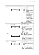
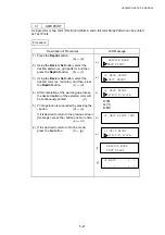
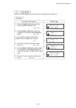
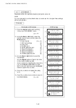
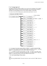
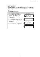
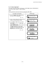
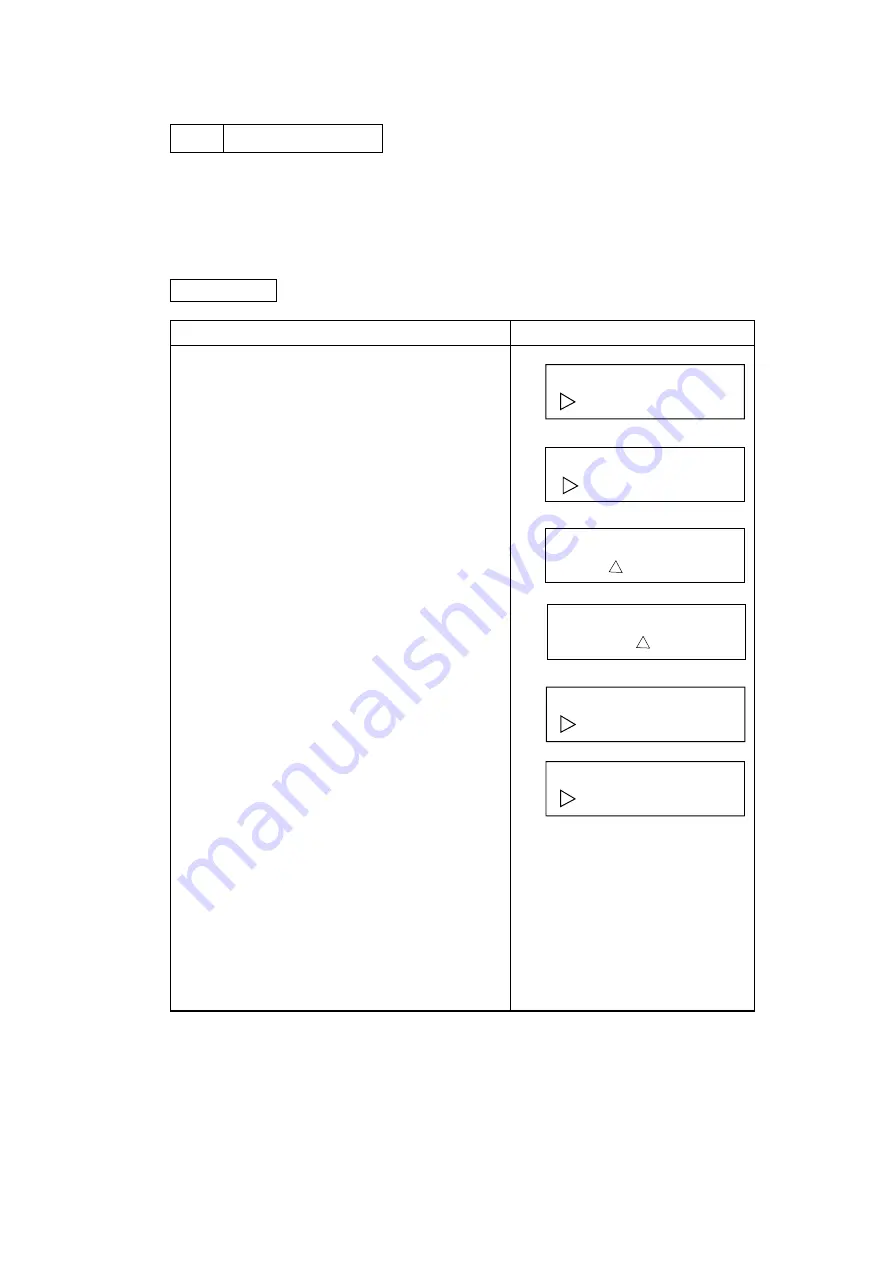
43 MARGIN
ADJUST
The position of the top margin and left margin can be confirmed and adjusted within the
range -3.5mm max. and +3.5mm max.
NOTE:
It is recommended to use the default value in normal use. Do not perform this mode
frequently.
Procedure
Description of Procedures
LCD Message
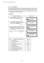
1) Press the Reprint button after selecting
Screen (a) “MARGIN ADJUST”.
(a)
o
(b)
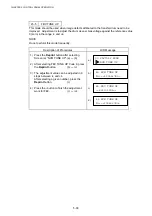
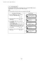
2) Using the Back or Set button, select one of
TOP, LEFT, LEFT1, LEFT2, LEFT3 and then
press the Reprint button.
(b)
o
(c)
LEFT: For adjustment of left edge of the
upper cassette.
LEFT1: For adjustment of left edge of the
lower cassette (1).
LEFT2: For adjustment of left edge of lower
cassette (2).
LEFT3: For adjustment of left edge from the
duplex unit.
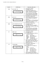
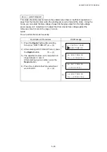
3) The margins can be adjusted by up to 3.5mm
left and right in 0.5mm steps from the
reference value “0”.
Using
the
Back or Set button, select the
amount of adjustment by selecting a number
displayed in screen (c) or (d). The amount of
adjustment selected will be displayed at the
upper right corner of Screen (c) or (d).
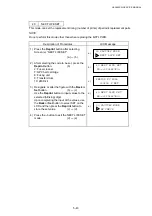
After confirming the desired amount of
adjustment is displayed, press the Reprint
button to set the adjustment.
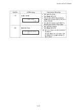
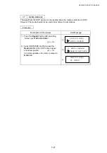
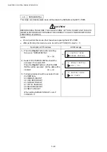
4) Press the - button to exit the MARGIN
ADJUST mode.
(d)
o
(e)
5) Press the - button one more time to return to
FACTORY MODE.
(e)
o
(f)
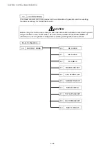
39 FACTORY MODE
MARGIN ADJUST
43 MARGIN ADJUST
43 TOP -2.0mm
-<765432101>+
a)
b)
c)
d)
e)
TOP/LEFT/LEFT1/LEFT2/LEFT3
43 TOP +2.5mm
-<101234567>+
43 MARGIN ADJUST
39 FACTORY MODE
DP CHECK
f)
TOP/LEFT/LEFT1/LEFT2/LEFT3
Summary of Contents for HL-3450CN Series
Page 15: ...HL 3450CN SERVICE MANUAL xiii 3 Rating Label For US For Europe 4 Operation Label 5 Jam Label ...
Page 17: ...HL 3450CN SERVICE MANUAL CHAPTER 1 PRODUCT OUTLINE ...
Page 27: ...HL 3450CN SERVICE MANUAL CHAPTER 2 SPECIFICATIONS ...
Page 39: ...CHAPTER 3 INSTALLATION ...
Page 54: ...HL 3450CN SERVICE MANUAL CHAPTER 4 STRUCTURE OF SYSTEM COMPONENTS ...
Page 104: ...HL 3450CN SERVICE MANUAL 4 51 Main PCB Circuit Diagram 1 8 CODE B512137CIR 1 8 LJ8907001 NAME ...
Page 106: ...HL 3450CN SERVICE MANUAL 4 53 Main PCB Circuit Diagram 3 8 CODE B512137CIR 3 8 LJ8907001 NAME ...
Page 108: ...HL 3450CN SERVICE MANUAL 4 55 Main PCB Circuit Diagram 5 8 CODE B512137CIR 5 8 LJ8907001 NAME ...
Page 110: ...HL 3450CN SERVICE MANUAL 4 57 Main PCB Circuit Diagram 7 8 CODE B512137CIR 7 8 LJ8907001 NAME ...
Page 126: ...HL 3450CN SERVICE MANUAL CHAPTER 5 CONTROL PANEL OPERATION ...
Page 173: ...HL 3450CN SERVICE MANUAL CHAPTER 6 PERIODIC MAINTENANCE ...
Page 208: ...CHAPTER 7 DISASSEMBLY RE ASSEMBLY ...
Page 264: ...HL 3450CN SERVICE MANUAL CHAPTER 8 TROUBLESHOOTING ...
Page 310: ...HL 3450CN SERVICE MANUAL 8 47 5 IMAGE FAILURE 1 2 3 4 5 6 7 8 9 a 9 b 10 11 12 13 14 ...
Page 311: ...CHAPTER 8 TROUBLESHOOTING 8 48 15 a 15 b 16 17 18 19 20 21 22 23 24 25 26 27 28 244m m 29 ...


