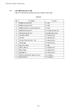

CHAPTER 5 CONTROL PANEL OPERATION
5-44
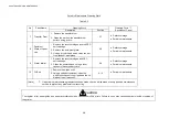
3.4
Adjustment Work Procedures
3.4.1
Adjustment of top and left margin
The top and left margins can be adjusted by button operation on the control panel.
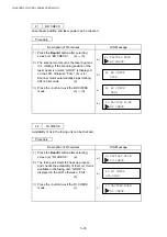
<Purpose>
If there is no top margin or left margin set for the print guarantee area or when the MCTL
PWB is replaced, the adjustment of top and left margin will be required.
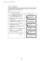
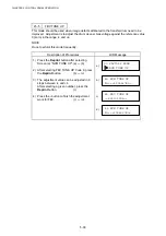
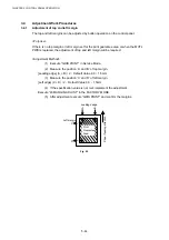
<Adjustment Method>
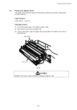
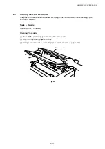
(1) Execute
“GRID PRINT” in Service Mode.
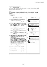
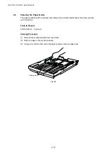
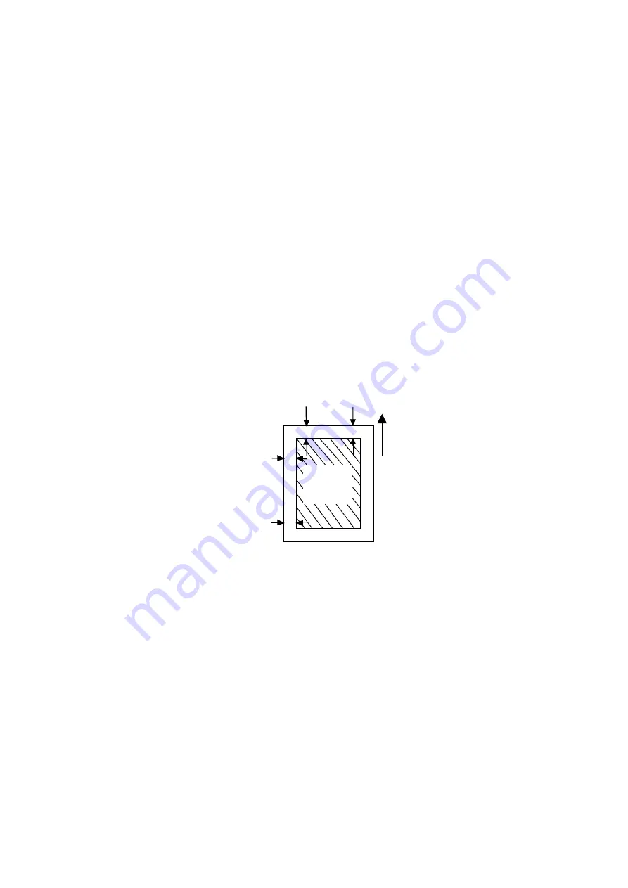
(2) Measure the position ‘A’ and ‘B’ of top margin.
[Leading edge] (A + B) / 2
d
Default Value 4.0
r
1.5mm
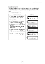
(3) Measure the position ‘C’ and ‘D’ of left margin.
[Left edge] (C + D) / 2
d
Default Value 3.0
r
1.5mm
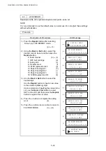
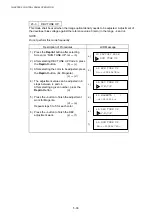
(4) If the specification value is not met, implement the adjustment.
Execute
“43 MARGIN ADJUST” in the FACTORY MODE.
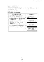
(5) After adjustment execute “GRID PRINT” and confirm the margins.
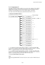
Guarantee
Area
Paper feeding direction
D
C
A
B
Leading dedge
Left margin
Fig. 5-2
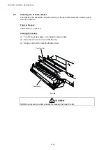
Summary of Contents for HL-3450CN Series
Page 15: ...HL 3450CN SERVICE MANUAL xiii 3 Rating Label For US For Europe 4 Operation Label 5 Jam Label ...
Page 17: ...HL 3450CN SERVICE MANUAL CHAPTER 1 PRODUCT OUTLINE ...
Page 27: ...HL 3450CN SERVICE MANUAL CHAPTER 2 SPECIFICATIONS ...
Page 39: ...CHAPTER 3 INSTALLATION ...
Page 54: ...HL 3450CN SERVICE MANUAL CHAPTER 4 STRUCTURE OF SYSTEM COMPONENTS ...
Page 104: ...HL 3450CN SERVICE MANUAL 4 51 Main PCB Circuit Diagram 1 8 CODE B512137CIR 1 8 LJ8907001 NAME ...
Page 106: ...HL 3450CN SERVICE MANUAL 4 53 Main PCB Circuit Diagram 3 8 CODE B512137CIR 3 8 LJ8907001 NAME ...
Page 108: ...HL 3450CN SERVICE MANUAL 4 55 Main PCB Circuit Diagram 5 8 CODE B512137CIR 5 8 LJ8907001 NAME ...
Page 110: ...HL 3450CN SERVICE MANUAL 4 57 Main PCB Circuit Diagram 7 8 CODE B512137CIR 7 8 LJ8907001 NAME ...
Page 126: ...HL 3450CN SERVICE MANUAL CHAPTER 5 CONTROL PANEL OPERATION ...
Page 173: ...HL 3450CN SERVICE MANUAL CHAPTER 6 PERIODIC MAINTENANCE ...
Page 208: ...CHAPTER 7 DISASSEMBLY RE ASSEMBLY ...
Page 264: ...HL 3450CN SERVICE MANUAL CHAPTER 8 TROUBLESHOOTING ...
Page 310: ...HL 3450CN SERVICE MANUAL 8 47 5 IMAGE FAILURE 1 2 3 4 5 6 7 8 9 a 9 b 10 11 12 13 14 ...
Page 311: ...CHAPTER 8 TROUBLESHOOTING 8 48 15 a 15 b 16 17 18 19 20 21 22 23 24 25 26 27 28 244m m 29 ...