
CHAPTER 7 DISASSEMBLY & RE-ASSEMBLY
7-4
CHAPTER 7
DISASSEMBLY & RE-ASSEMBLY
1. BEFORE STARTING DISASSEMBLY
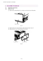
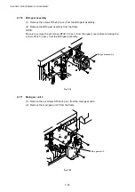
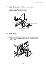
1.1
Precautions
Follow the precautions described below during maintenance work.
(1) Do not implement any operation, disassembly or modification which is not set out in this
manual.
(2) This printer incorporates dangerous parts subject to warnings such as “High
Temperature”, “High Voltage” and “Laser Radiation”. Before starting any work on this
printer, make sure you have read and understand the warnings set out in this manual.
(3) Collect and dispose of any waste toner cartridges removed during maintenance correctly
in accordance with local regulations. Do not dispose of them with inflammable materials
or dispose of them into a fire.
(4) The grounding wire is disconnected when replacing or removing the DC power supply
unit. After completing the replacement work, confirm that the grounding wire is
reconnected correctly to the earth mark
.
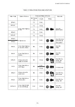
(5) Ensure that the type and length of screws removed during replacement of maintenance
parts is noted and the correct screws are used during re-assembly. (See Table 7-1.)
(6) Do not use any solvent such as alcohol for the maintenance of this printer.
(7) Confirm that all the parts and covers are installed or assembled correctly before starting
the test run after replacement of maintenance parts.
(8) The re-assembly order is the reverse of the dis-assembly order. In all cases, follow the
flow chart in reverse to re-assemble the printer. Where there is any change to the order,
this is noted in the relevant section.
1.2
Preparation of Disassembly
Follow the procedure described below for preparation before commencing any work.
(1) Ensure that the power cable is disconnected from the power outlet.
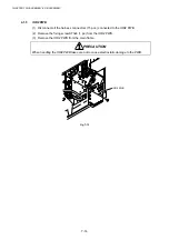
(2) Remove
all consumable parts (OPC belt cartridge, fuser cleaner, oil bottle, all toner
cartridges, ozone filter), the Main (Video controller) PCB, Fusing unit and Fuser
cleaner, and then store them correctly before starting disassembly.
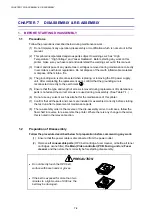
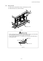
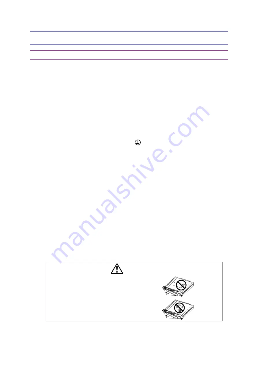
PRECAUTION
x
Do not directly touch the OPC belt
surface with bare hands or gloves.
x
If the belt is exposed for more than two
minutes to a light source of 800 lux, the
belt may be damaged.
Summary of Contents for HL-3450CN Series
Page 15: ...HL 3450CN SERVICE MANUAL xiii 3 Rating Label For US For Europe 4 Operation Label 5 Jam Label ...
Page 17: ...HL 3450CN SERVICE MANUAL CHAPTER 1 PRODUCT OUTLINE ...
Page 27: ...HL 3450CN SERVICE MANUAL CHAPTER 2 SPECIFICATIONS ...
Page 39: ...CHAPTER 3 INSTALLATION ...
Page 54: ...HL 3450CN SERVICE MANUAL CHAPTER 4 STRUCTURE OF SYSTEM COMPONENTS ...
Page 104: ...HL 3450CN SERVICE MANUAL 4 51 Main PCB Circuit Diagram 1 8 CODE B512137CIR 1 8 LJ8907001 NAME ...
Page 106: ...HL 3450CN SERVICE MANUAL 4 53 Main PCB Circuit Diagram 3 8 CODE B512137CIR 3 8 LJ8907001 NAME ...
Page 108: ...HL 3450CN SERVICE MANUAL 4 55 Main PCB Circuit Diagram 5 8 CODE B512137CIR 5 8 LJ8907001 NAME ...
Page 110: ...HL 3450CN SERVICE MANUAL 4 57 Main PCB Circuit Diagram 7 8 CODE B512137CIR 7 8 LJ8907001 NAME ...
Page 126: ...HL 3450CN SERVICE MANUAL CHAPTER 5 CONTROL PANEL OPERATION ...
Page 173: ...HL 3450CN SERVICE MANUAL CHAPTER 6 PERIODIC MAINTENANCE ...
Page 208: ...CHAPTER 7 DISASSEMBLY RE ASSEMBLY ...
Page 264: ...HL 3450CN SERVICE MANUAL CHAPTER 8 TROUBLESHOOTING ...
Page 310: ...HL 3450CN SERVICE MANUAL 8 47 5 IMAGE FAILURE 1 2 3 4 5 6 7 8 9 a 9 b 10 11 12 13 14 ...
Page 311: ...CHAPTER 8 TROUBLESHOOTING 8 48 15 a 15 b 16 17 18 19 20 21 22 23 24 25 26 27 28 244m m 29 ...