
HL-3450CN SERVICE MANUAL
7-47
4.5
Front of the Printer
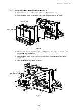
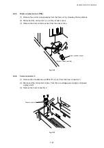
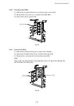
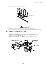
4.5.1
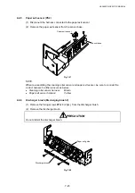
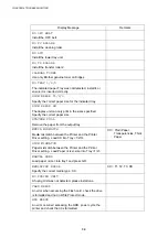
Front outer cover (Front cover 3)
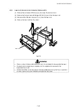
(1) Open the front cover unit 3.
(2) Remove the set screws BT4x10 (2 pcs.) from the front cover unit 3.
(3) Unhook the five hooks and remove the front outer cover.
Fig. 7-70
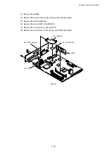
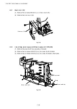
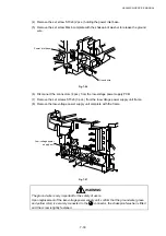
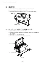
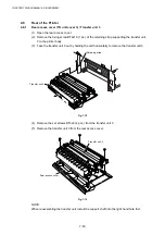
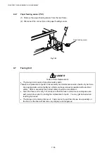
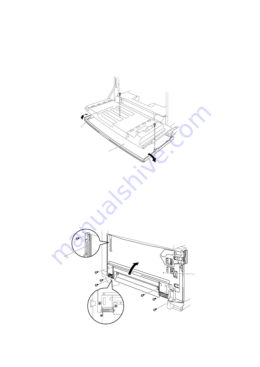
4.5.2
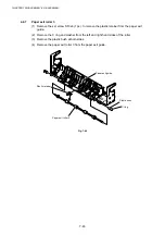
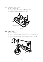
Front cover unit 3
(1) Close the front cover.
(2) Remove the set screw ST4x6 (6 pcs.) to remove the front cover supports at left and right
sides from the frame.
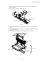
(3) Remove the set screw ST3x6 (1 pc.) from the front hinge (L) to remove the front hinge
support from the frame.
Fig. 7-71
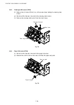
Hook
Front outer cover
Front hinge support
Front cover
Summary of Contents for HL-3450CN Series
Page 15: ...HL 3450CN SERVICE MANUAL xiii 3 Rating Label For US For Europe 4 Operation Label 5 Jam Label ...
Page 17: ...HL 3450CN SERVICE MANUAL CHAPTER 1 PRODUCT OUTLINE ...
Page 27: ...HL 3450CN SERVICE MANUAL CHAPTER 2 SPECIFICATIONS ...
Page 39: ...CHAPTER 3 INSTALLATION ...
Page 54: ...HL 3450CN SERVICE MANUAL CHAPTER 4 STRUCTURE OF SYSTEM COMPONENTS ...
Page 104: ...HL 3450CN SERVICE MANUAL 4 51 Main PCB Circuit Diagram 1 8 CODE B512137CIR 1 8 LJ8907001 NAME ...
Page 106: ...HL 3450CN SERVICE MANUAL 4 53 Main PCB Circuit Diagram 3 8 CODE B512137CIR 3 8 LJ8907001 NAME ...
Page 108: ...HL 3450CN SERVICE MANUAL 4 55 Main PCB Circuit Diagram 5 8 CODE B512137CIR 5 8 LJ8907001 NAME ...
Page 110: ...HL 3450CN SERVICE MANUAL 4 57 Main PCB Circuit Diagram 7 8 CODE B512137CIR 7 8 LJ8907001 NAME ...
Page 126: ...HL 3450CN SERVICE MANUAL CHAPTER 5 CONTROL PANEL OPERATION ...
Page 173: ...HL 3450CN SERVICE MANUAL CHAPTER 6 PERIODIC MAINTENANCE ...
Page 208: ...CHAPTER 7 DISASSEMBLY RE ASSEMBLY ...
Page 264: ...HL 3450CN SERVICE MANUAL CHAPTER 8 TROUBLESHOOTING ...
Page 310: ...HL 3450CN SERVICE MANUAL 8 47 5 IMAGE FAILURE 1 2 3 4 5 6 7 8 9 a 9 b 10 11 12 13 14 ...
Page 311: ...CHAPTER 8 TROUBLESHOOTING 8 48 15 a 15 b 16 17 18 19 20 21 22 23 24 25 26 27 28 244m m 29 ...


