
HL-3450CN SERVICE MANUAL
8-13
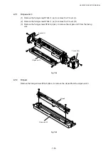
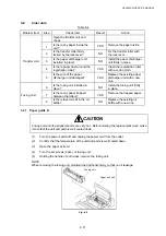
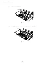
(8)
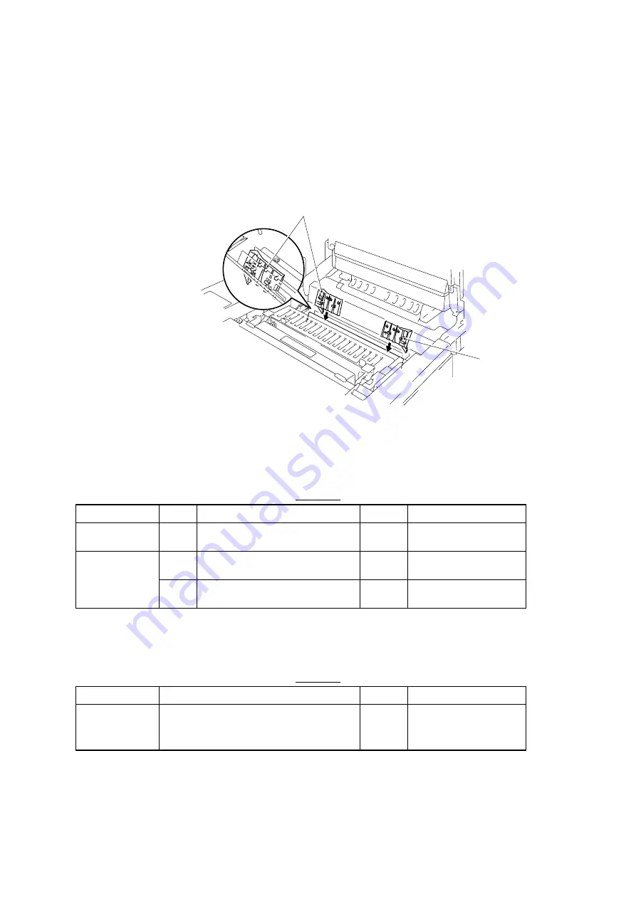
Install a new paper guide D (with a pawl for separating paper). Attend the orientation
of installation.
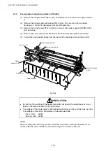
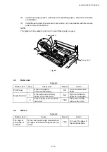
(9)
Install the each parts (the oil sensor cover and so on) in accordance with the reverse
order of remove procedures.
NOTE:
This printer will be unable to print on A3+ size if these parts are used.
Fig. 8-5
3.3
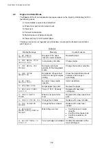
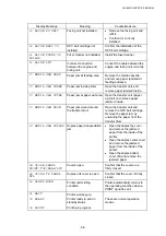
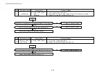
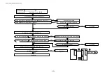
Outer Jam
Table 8-5
Problem Item
Step
Check Item
Result
Action
Print Paper
1
Is the print paper a
recommended paper?
NO
Use a recommended
paper.
Paper Exit Unit
1
Is the paper exit unit firmly
locked by the lock lever?
NO
Open and close the
paper exit unit again.
2
Is there paper dust around the
exit roller?
YES
Clean the exit roller
with a cotton cloth.
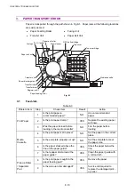
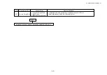
3.4
Others
Table 8-6
Problem Item
Cause
Result
Action
The edge of
print paper is
creased.
Is the curled paper edge creased when
the paper is loaded through the pick-up
roller?
YES
Turn over the paper in
the media cassette.
Paper guide D
Paper guide D
Summary of Contents for HL-3450CN Series
Page 15: ...HL 3450CN SERVICE MANUAL xiii 3 Rating Label For US For Europe 4 Operation Label 5 Jam Label ...
Page 17: ...HL 3450CN SERVICE MANUAL CHAPTER 1 PRODUCT OUTLINE ...
Page 27: ...HL 3450CN SERVICE MANUAL CHAPTER 2 SPECIFICATIONS ...
Page 39: ...CHAPTER 3 INSTALLATION ...
Page 54: ...HL 3450CN SERVICE MANUAL CHAPTER 4 STRUCTURE OF SYSTEM COMPONENTS ...
Page 104: ...HL 3450CN SERVICE MANUAL 4 51 Main PCB Circuit Diagram 1 8 CODE B512137CIR 1 8 LJ8907001 NAME ...
Page 106: ...HL 3450CN SERVICE MANUAL 4 53 Main PCB Circuit Diagram 3 8 CODE B512137CIR 3 8 LJ8907001 NAME ...
Page 108: ...HL 3450CN SERVICE MANUAL 4 55 Main PCB Circuit Diagram 5 8 CODE B512137CIR 5 8 LJ8907001 NAME ...
Page 110: ...HL 3450CN SERVICE MANUAL 4 57 Main PCB Circuit Diagram 7 8 CODE B512137CIR 7 8 LJ8907001 NAME ...
Page 126: ...HL 3450CN SERVICE MANUAL CHAPTER 5 CONTROL PANEL OPERATION ...
Page 173: ...HL 3450CN SERVICE MANUAL CHAPTER 6 PERIODIC MAINTENANCE ...
Page 208: ...CHAPTER 7 DISASSEMBLY RE ASSEMBLY ...
Page 264: ...HL 3450CN SERVICE MANUAL CHAPTER 8 TROUBLESHOOTING ...
Page 310: ...HL 3450CN SERVICE MANUAL 8 47 5 IMAGE FAILURE 1 2 3 4 5 6 7 8 9 a 9 b 10 11 12 13 14 ...
Page 311: ...CHAPTER 8 TROUBLESHOOTING 8 48 15 a 15 b 16 17 18 19 20 21 22 23 24 25 26 27 28 244m m 29 ...


