
HL-3450CN SERVICE MANUAL
4-3
CHAPTER 4
STRUCTURE OF SYSTEM COMPONENTS
1. BASIC
STRUCTURE
1.1
Mechanical Structures
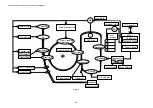
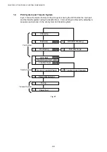
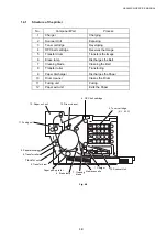
This laser beam color printer (hereinafter called “Printer”) consists of five mechanical
systems; Print, Transfer, Scanning, Paper Transport and Control System. The printer
produces color printing through the interactive operations of these five systems as shown in
Fig.4-1.
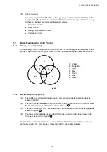
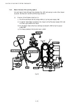
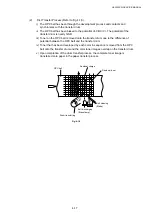
(1) Print
System
The print system consists of the following 6 (six) functional parts located around the
OPC belt which form a toner image on the OPC Belt.
x
Charger Part
x
Exposure Part
x
Development Part
x
First Transfer Part
x
Discharger Part
x
Cleaner Part
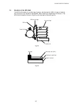
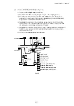
(2) Scanning
System
The scanning system consists of the following 2 (two) functional parts which form an
electrostatic latent image on the OPC Belt by scanning it with a laser beam.
x
Scanner Unit
x
Scanner Motor (SCM)
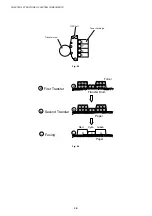
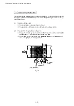
(3) Transfer
System
The transfer system consists of the following 3 (three) functional parts and transfers
the toner image formed on the transfer drum onto the page.
x
Transfer Drum
x
Second Transfer Part
x
Drum Cleaner Unit
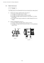
(4)
Paper Transport System
The paper transport system consists of the following 5 (five) functional parts and picks
up paper from the media cassette, separates the paper from the transfer drum and
exits it from the printer body after fusing the toner image on the paper.
x
Media Cassette
x
Transport rollers
x
Paper Discharger
x
Fusing unit
x
Paper Exit
Summary of Contents for HL-3450CN Series
Page 15: ...HL 3450CN SERVICE MANUAL xiii 3 Rating Label For US For Europe 4 Operation Label 5 Jam Label ...
Page 17: ...HL 3450CN SERVICE MANUAL CHAPTER 1 PRODUCT OUTLINE ...
Page 27: ...HL 3450CN SERVICE MANUAL CHAPTER 2 SPECIFICATIONS ...
Page 39: ...CHAPTER 3 INSTALLATION ...
Page 54: ...HL 3450CN SERVICE MANUAL CHAPTER 4 STRUCTURE OF SYSTEM COMPONENTS ...
Page 104: ...HL 3450CN SERVICE MANUAL 4 51 Main PCB Circuit Diagram 1 8 CODE B512137CIR 1 8 LJ8907001 NAME ...
Page 106: ...HL 3450CN SERVICE MANUAL 4 53 Main PCB Circuit Diagram 3 8 CODE B512137CIR 3 8 LJ8907001 NAME ...
Page 108: ...HL 3450CN SERVICE MANUAL 4 55 Main PCB Circuit Diagram 5 8 CODE B512137CIR 5 8 LJ8907001 NAME ...
Page 110: ...HL 3450CN SERVICE MANUAL 4 57 Main PCB Circuit Diagram 7 8 CODE B512137CIR 7 8 LJ8907001 NAME ...
Page 126: ...HL 3450CN SERVICE MANUAL CHAPTER 5 CONTROL PANEL OPERATION ...
Page 173: ...HL 3450CN SERVICE MANUAL CHAPTER 6 PERIODIC MAINTENANCE ...
Page 208: ...CHAPTER 7 DISASSEMBLY RE ASSEMBLY ...
Page 264: ...HL 3450CN SERVICE MANUAL CHAPTER 8 TROUBLESHOOTING ...
Page 310: ...HL 3450CN SERVICE MANUAL 8 47 5 IMAGE FAILURE 1 2 3 4 5 6 7 8 9 a 9 b 10 11 12 13 14 ...
Page 311: ...CHAPTER 8 TROUBLESHOOTING 8 48 15 a 15 b 16 17 18 19 20 21 22 23 24 25 26 27 28 244m m 29 ...


