
HL-3450CN SERVICE MANUAL
6-23
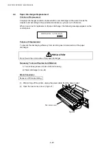
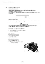
4.2
Fusing Unit Replacement
Criterion of Replacement
The fusing unit should be replaced with a new one according to the periodical maintenance
cycle set out in Table 6-4.
When the time is due for replacement of the fusing unit, the following message appears on
the control panel.
REPLACE FUSER
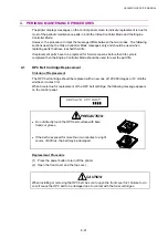
Purpose of Replacement
To prevent the print quality from declining due to the deterioration of the fixing unit’s fuser
rollers.
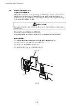
WARNING
The fusing unit and its surrounding area are very hot. Make sure prior to starting the
replacement work that the fusing unit and its surrounding area are well cooled down,
otherwise you may get burned.
Necessary Tools and Replacement Materials
x
Two or three pieces of cotton cloth for cleaning
x
Fusing unit (one unit)
Work Procedure
Sequence of Disassembling
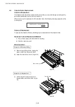
(1) After turning off the printer, unplug the power cable from the power outlet.
(2) Open the top cover.
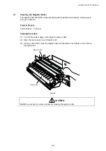
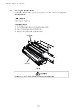
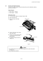
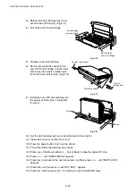
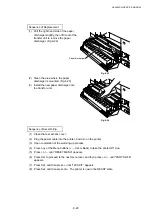
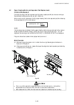
(3) Remove the two screws securing the
fusing unit. (Fig.6-14)
Fig. 6-15
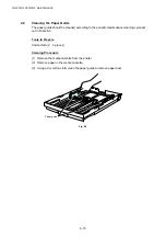
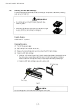
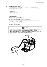
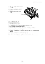
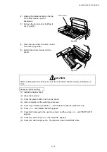
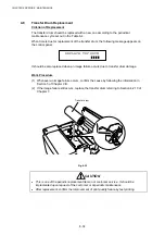
(4) Holding the handles at both ends of
the fusing unit and remove the fusing
unit from the printer. (Fig.6-15)
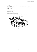
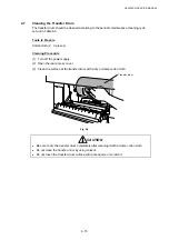
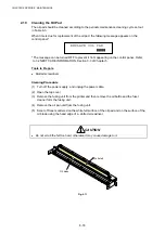
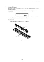
(5) Remove the oil bottle and the fuser
cleaner.
Fig. 6-16
Screw
Screw
Fusing unit
Summary of Contents for HL-3450CN Series
Page 15: ...HL 3450CN SERVICE MANUAL xiii 3 Rating Label For US For Europe 4 Operation Label 5 Jam Label ...
Page 17: ...HL 3450CN SERVICE MANUAL CHAPTER 1 PRODUCT OUTLINE ...
Page 27: ...HL 3450CN SERVICE MANUAL CHAPTER 2 SPECIFICATIONS ...
Page 39: ...CHAPTER 3 INSTALLATION ...
Page 54: ...HL 3450CN SERVICE MANUAL CHAPTER 4 STRUCTURE OF SYSTEM COMPONENTS ...
Page 104: ...HL 3450CN SERVICE MANUAL 4 51 Main PCB Circuit Diagram 1 8 CODE B512137CIR 1 8 LJ8907001 NAME ...
Page 106: ...HL 3450CN SERVICE MANUAL 4 53 Main PCB Circuit Diagram 3 8 CODE B512137CIR 3 8 LJ8907001 NAME ...
Page 108: ...HL 3450CN SERVICE MANUAL 4 55 Main PCB Circuit Diagram 5 8 CODE B512137CIR 5 8 LJ8907001 NAME ...
Page 110: ...HL 3450CN SERVICE MANUAL 4 57 Main PCB Circuit Diagram 7 8 CODE B512137CIR 7 8 LJ8907001 NAME ...
Page 126: ...HL 3450CN SERVICE MANUAL CHAPTER 5 CONTROL PANEL OPERATION ...
Page 173: ...HL 3450CN SERVICE MANUAL CHAPTER 6 PERIODIC MAINTENANCE ...
Page 208: ...CHAPTER 7 DISASSEMBLY RE ASSEMBLY ...
Page 264: ...HL 3450CN SERVICE MANUAL CHAPTER 8 TROUBLESHOOTING ...
Page 310: ...HL 3450CN SERVICE MANUAL 8 47 5 IMAGE FAILURE 1 2 3 4 5 6 7 8 9 a 9 b 10 11 12 13 14 ...
Page 311: ...CHAPTER 8 TROUBLESHOOTING 8 48 15 a 15 b 16 17 18 19 20 21 22 23 24 25 26 27 28 244m m 29 ...


