HL-6050/6050D/6050DN SERVICE MANUAL
4-51
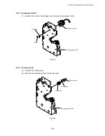
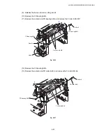
3.41 Toner Sensor PCB Unit
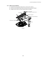
(1) Remove the cup S M3x6 Taptite screw, and remove the toner sensor PCB unit.
Fig. 4-95
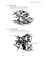
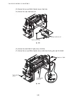
3.42 HVPS PCB ASSY
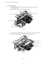
(1) Remove the two bind B M4x10 Taptite screws, and remove the insulation sheet HVPS.
(2) Disconnect the connector from the HVPS PCB ASSY.
(3) Remove the two bind B M4x10 Taptite screws, and remove the HVPS PCB ASSY.
Fig. 4-96
Taptite, bind B M4x10
Taptite, bind B M4x10
Insulation sheet HVPS
HVPS PCB ASSY
Taptite, cup S M3x6
Toner sensor PCB unit
Connector


