HL-6050/6050D/650DN SERVICE MANUAL
6-27
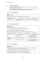
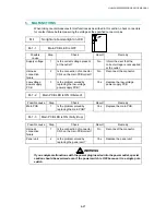
5. MALFUNCTIONS
When taking countermeasures for malfunctions as described in this section, check connectors
for contact failure before measuring the voltage at the specified connector pins.
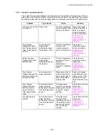
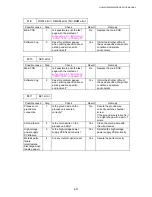
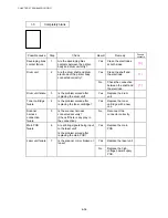
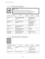
M-1
No light or abnormal light on LCD
M-1-1
Main PCB LED is OFF
Possible
cause
Step Check Result
Remedy
Supply voltage
1
Is the correct voltage present
at the outlet?
No
Inform the user that the
correct voltage is not supplied
at the outlet.
Harness
connection
failure
2
Is the connection of connector
CN4 on the main PCB correct?
No
Reconnect the connector.
Low-voltage
power supply
PCB
3
Is the problem solved by
replacing the low-voltage
power supply PCB?
Yes
Replace the low-voltage
power supply PCB.
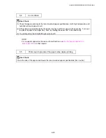
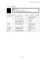
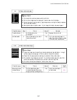
M-1-2
Main PCB LED is ON (Dimmed)
Possible cause
Step
Check
Result
Remedy
Main PCB
1
Is the problem solved by
replacing the main PCB?
Yes
Replace the main PCB.
M-1-3
Main PCB LED is ON (Fully lit up)
Possible cause
Step
Check
Result
Remedy
Harness
connection
failure
1
Is the connection of connector
CN3 on the main PCB correct?
No
Reconnect the connector.
Panel unit
2
Is the problem solved by
replacing the panel unit?
Yes
Replace the panel unit.
WARNING
If you analyze malfunctions with the power plug inserted into the power outlet, special
caution should be exercised even if the power switch is OFF because it is a single pole
switch.

