HL-6050/6050D/6050DN SERVICE MANUAL
3-13
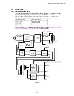
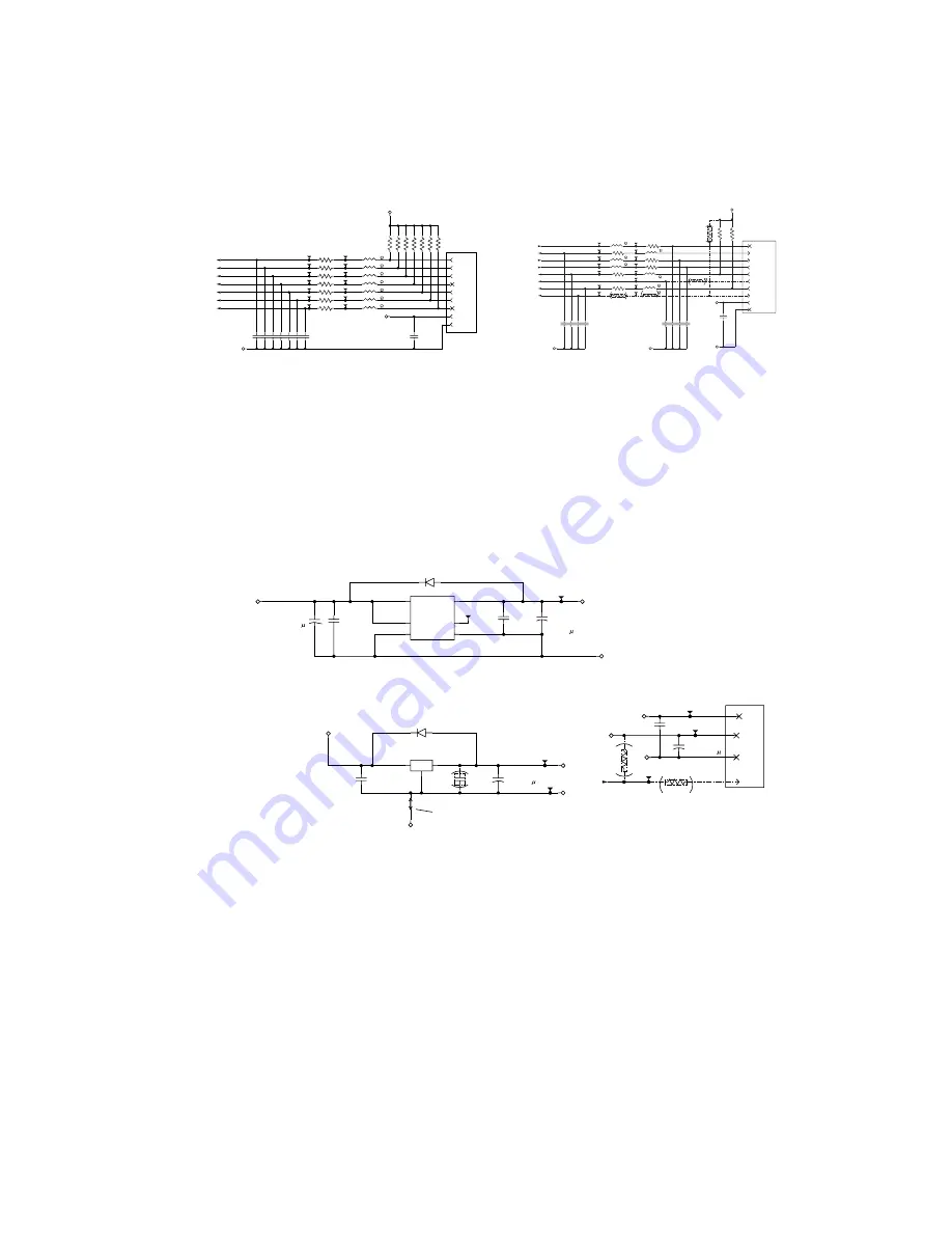
1.3.15 Sensor I/O
Each sensor of Pre-Regist, Regist, T1-PE, Plate, MP-PE, DX-Size, DX-Jam, Rear tray, Front
cover, and DEV is connected to ASIC port on the main PC board and to be read with a
software.
L27
0
L26
0
L31
0
L29
0
L32
0
L30
0
L28
0
C45
C101
R56 100
R57 100
R61 100
R60 100
R59 100
R58 100
R62 100
TP43
TP44
TP48
TP47
TP49
TP46
TP45
2E
MPPE
1E
REG
1E
DXJAM
1-4C
PREREG
1D
T1-PE
1D
DX-SIZE
1D
T1-PLATE
C46
C101
C50
C101
C49
C101
C51
C101
C48
C101
C47
C101
0V
C1
C103
R32
R33
R37
R36
R38
R35
R34
68k
68k
68k
68k
68k
68k
68k
VDD3
TP55
TP60
TP57
TP56
TP58
TP59
TP61
1
PRE-REG
2
REG
3
SEN3
4
DX-JAM
5
DX-SIZE
6
0V
7
T1-PLATE
CN1
B09B-CZHK-B-1
8
T1-PE
9
MP-PE
SEN3.3V
TP24
C22
C101
C16
C101
R16
100
C15
C101
R18
100
L12
0
C18
C101
C19
C101
TP2
C17
C101
VDD5
2D
PNLRST
2D
PNLSDO
1-6E/5-7C
COVER/VDD5I
1-4C
REARTRAY
2E
PNLSDIN
R15
100
R17
100
R21
100
R13 100
1-4C
DEVVER
L18
0
L16
0
L15
0
L13
0
TP26
TP4
TP28
TP23
TP22
TP25
TP1
TP3
TP29
2D
PNLCLK
L14
0
C21
C103
C14
C103
TP5
R20
4.7k
R14
4.7k
VDD3
1E
FULL
C20
10k
R19
100
TP6
TP27
L17
0
1
REAR TRAY
2
+5V
CN3
B10B-CZHK-B-1
3
FULL
4
PNLCLK
5
SDOUT
6
SDIN
7
PNLRSTN
8
0V
9
DEV-VER
10
COVER/VDD5I
L11
0
(1608)
TP21
0V
0V
0V
R200
4.7k
PANEL
Fig. 3-17
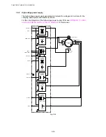
1.3.16 Power Supply
+5V is generated by the 3-pin regulator from astable 7V supplied from the LVPS. +5V is used
for the IEEE1284 interface, the LD PCB and the engine PCB. In addition, +1.9V is generated
by the 3-pin regulator from 3.3V supplied from the LVPS. +1.9V is used for the CPU within
the ASIC and the logic circuit.
+
+
+
+
C100
C104
C26
C104
VDD1.9
VDD8
D1
RB751V-40
C27
C10
16V
Q1
NJM2391DL1-05-TE1
OUT
IN
GND
VDD5
C102
C220
6.3V 6V
C25
C104
0V
0V
VDD3
D2
RB751V-40
OT1
C99
C10
16V
C101
C104
C23
C220
6.3V 6V
0V
VDD3
VDD8
3C
SLEEP
R3
33
TP198
TP30
1
0V
CN4
2
+3.3V
3
+8V
B4B-EH-A
4
SLEEP
R2
68k
C24
C104
FG1
U10
R1170S191B
VDD
6
CE
3
GND2
2
VOUT
1
GND4
4
GND5
5
TP403
TP404
TP402
TP401
TP400
(WHITE)
LVPS
4PIN OPEN
Fig. 3-18


