USER’S GUIDE
CHAPTER 5 –8
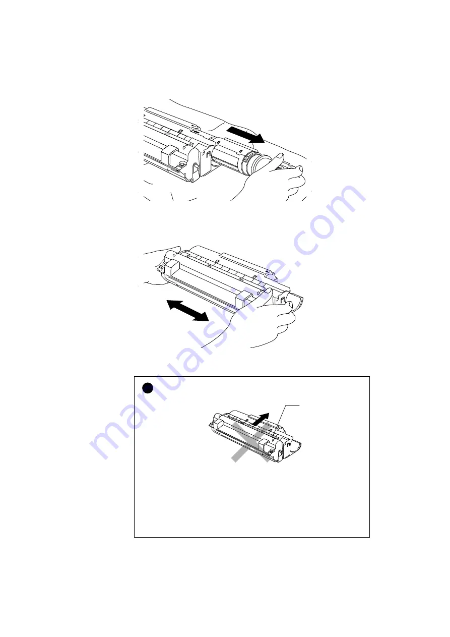
Fig. 5-12 Removing the Toner Cartridge
4. Unpack the drum unit and gently shake it five or six times horizontally.
Fig. 5-13 Shaking the Drum Unit
!
Caution
•
Do not remove the starter sheet.
Fig. 5-14 Do Not Remove the Starter Sheet
•
Only unpack a drum unit immediately before installing it into the
printer. If an unpacked drum unit is subjected to excessive direct
sunlight or room light, the unit may be damaged.
•
Handle the toner cartridge and the drum unit carefully as it contains
toner. If toner scatters and your hands or clothes get dirty, wipe or wash
it off with cold water immediately.
Starter Sheet
Summary of Contents for HL-720
Page 1: ...SERVICE MANUAL MODEL HL 720 730 730Plus R LASER PRINTER ...
Page 36: ...II 19 1 3 10 Engine I O HL 720 Fig 2 21 shows the engine interface circuit Fig 2 21 ...
Page 37: ...II 20 HL 730 730Plus Fig 2 22 shows the engine interface circuit Fig 2 22 ...
Page 61: ... Fig 3 18 2 4 1 1 1 ...
Page 92: ...SERVICE MANUAL MODEL HL 760 R LASER PRINTER ...
Page 109: ...II 8 1 3 4 DRAM Two 4M bit DRAMs x 16bits are used as the RAM Fig 2 6 ...
Page 113: ...II 12 1 3 10 Engine I O Fig 2 12 shows the engine interface circuit Fig 2 12 ...
Page 114: ...II 13 1 3 11 Paper Feed Motor Drive Circuit Fig 2 13 ...
Page 133: ...Appendix 2 Main PCB Circuit Diagram 1 3 CODE UK3227000 B48K272CIR 1 3 NAME ...
Page 134: ...Appendix 3 Main PCB Circuit Diagram 2 3 CODE UK3227000 B48K272CIR 2 3 NAME ...
Page 135: ...CODE UK3227000 B48K272CIR 3 3 NAME Appendix 4 Main PCB Circuit Diagram 3 3 ...


