3-56
Confidential
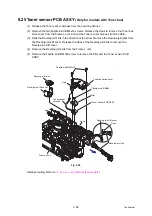
9.25 Toner sensor PCB ASSY
(Only for models with Toner box)
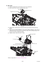
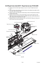
(1) Release the Toner sensor harness from the securing fixtures.
(2) Remove the two Taptite bind B M4x12 screws. Release the Hook to remove the Toner box
drive cover from the Frame L unit. Pull out the Toner sensor harness from the Hole.
(3) Slide the Develop joint link in the direction of the arrow. Remove the Develop joint disk from
the Develop joint lift cover. Release the Hook of the Develop joint link to remove the
Develop joint lift cover.
(4) Remove the Develop joint link from the Frame L unit.
(5) Remove the Taptite bind B M3x8 screw to remove the Film and the Toner sensor PCB
ASSY.
Fig. 3-55
Harness routing: Refer to
“4. Frame L unit (Manual feed models)”
.
Taptite bind B M3x8
Taptite bind B M4x12
Hole
Develop joint disk
Develop joint lift cover
Film
Toner sensor PCB ASSY
Toner sensor
harness
Develop joint lift cover
Hook
Develop joint link
Toner box drive cover
Hook
Frame L unit

