background image

2-42

Confidential

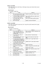
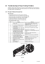
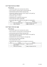
Electrodes location of main body

Fig. 2-8

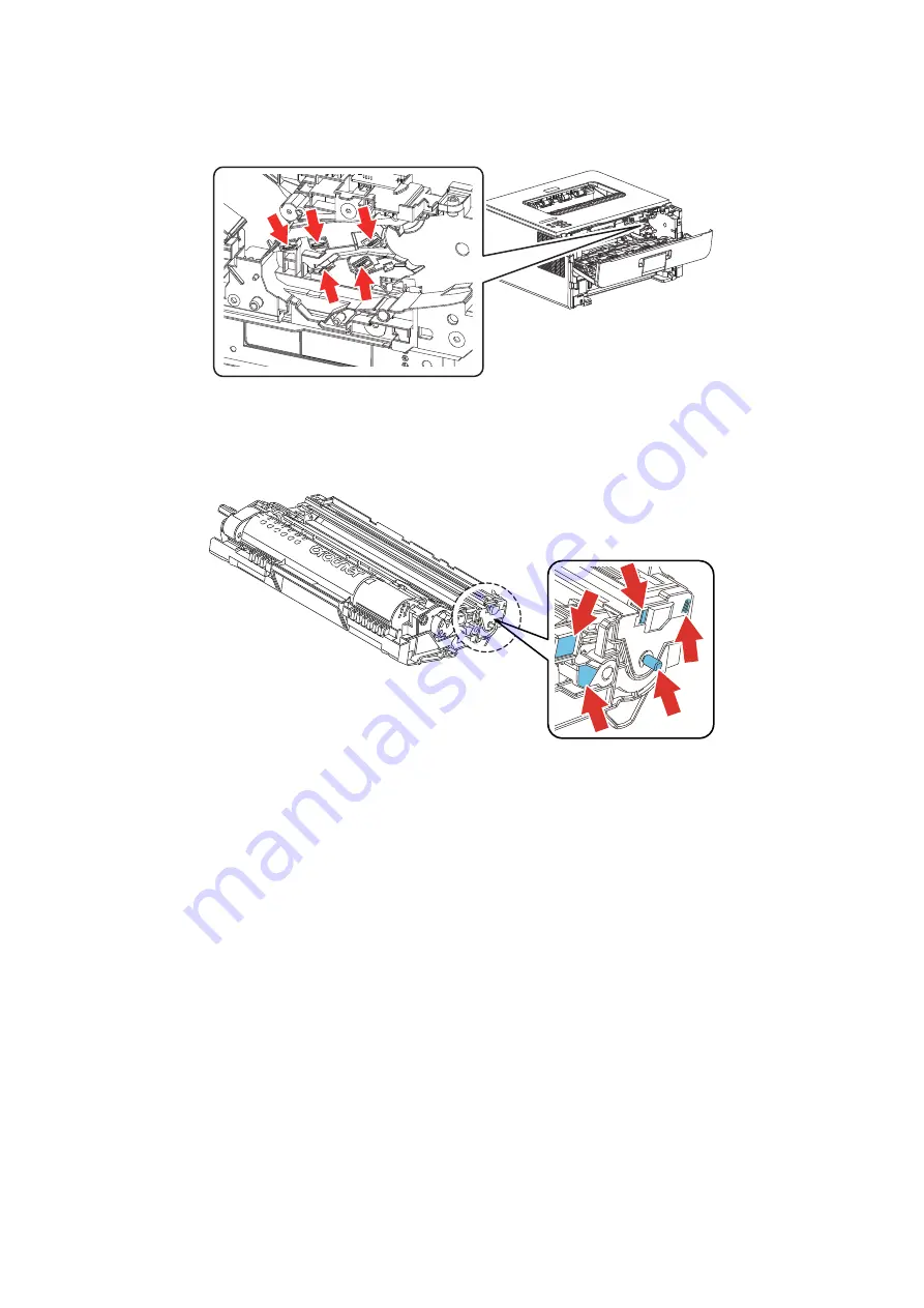
Electrodes location of the drum unit and process unit

Fig. 2-9

Summary of Contents for HL-B2080DW

Page 1: ...ick and easy reference at all times August 2017 SM PRN111 84UH Ver 4 Brother Laser Printer SERVICE MANUAL HL 2290 2295D 2590DN 2595DW B2000D B2050DN B2080DW L2310D L2312D L2325DW L2330D L2331D L2335D L2336D L2350DW L2351DW L2352DW L2357DW L2370DN L2370DW XL L2371DN L2372DN L2375DW L2376DW L2385DW L2386DW MODEL ...

Page 2: ...egistered trademarks and service marks of Mopria Alliance Inc in the United States and other countries Unauthorized use is strictly prohibited Each company whose software title is mentioned in this manual has a Software License Agreement specific to its proprietary programs Software Trademarks FlashFX is a registered trademark of Datalight Inc FlashFX Pro is a trademark of Datalight Inc FlashFX Te...

Page 3: ...formation Copyright and License 2017 Brother Industries Ltd All rights reserved This product includes software developed by the following vendors 1983 1998 PACIFIC SOFTWORKS INC ALL RIGHTS RESERVED 2008 Devicescape Software Inc All rights reserved This product includes the KASAGO TCP IP software developed by ZUKEN ELMIC Inc Copyright 1989 2014 Datalight Inc All Rights Reserved FlashFX Copyright 19...

Page 4: ...NDICATIONS 2 13 3 1 Error Codes 2 13 3 2 Error Message 2 21 3 2 1 LCD models 2 21 3 2 2 LED Display LED Models 2 27 4 TROUBLESHOOTING 2 33 4 1 Error Cause and Remedy 2 33 4 2 Troubleshooting for Paper Feeding Problems 2 53 4 2 1 No paper feeding from paper tray 2 53 4 2 2 No paper feeding from MP tray 2 54 4 2 3 No paper feeding from manual feed slot 2 55 4 2 4 Multiple sheets of paper are fed 2 5...

Page 5: ... replacement message displayed on LCD is not cleared 2 82 4 8 Troubleshooting for Fuser Unit Problems 2 83 4 8 1 Fuser unit failure 2 83 4 9 Troubleshooting for Laser Unit Problems 2 83 4 9 1 Laser unit failure 2 83 4 10 Troubleshooting for PCB Problems 2 84 4 10 1 Main PCB failure 2 84 4 10 2 Full memory 2 84 4 11 Troubleshooting for Other Problems 2 85 4 11 1 Cannot make print 2 85 4 11 2 Cannot...

Page 6: ... L unit 3 50 9 23 Paper feed motor Paper feed motor flat cable 3 53 9 24 Fuser gear 64R 36R 3 55 9 25 Toner sensor PCB ASSY Only for models with Toner box 3 56 9 26 Front cover sensor 3 57 9 27 Eject sensor PCB ASSY 3 58 9 28 Registration front rear actuator holder ASSY 3 60 9 29 Paper feed roller ASSY Paper feed sensor PCB ASSY 3 63 CHAPTER 4 ADJUSTING AND UPDATING SETTINGS AS REQUIRED AFTER PART...

Page 7: ... 1 3 10 Change USB No return value Adjust left end print position Adjust upper end print position Change ON OFF setting for lower case compensation Change ON OFF setting for fixation strength improvement Function code 45 5 18 1 3 11 Check toner cartridge Models with cartridge sensor only Function code 57 5 22 1 3 12 Continuous print test Function code 67 5 24 1 3 13 Print frame pattern single side...

Page 8: ...vice personnel 5 51 2 OTHER SERVICE FUNCTIONS 5 52 2 1 Print Printer Settings 5 52 2 2 Drum Cleaning 5 54 2 3 Resetting Drum Counter 5 56 2 4 Change Active Inactive Setting for Quiet Mode LED models only 5 56 2 5 Change Active Inactive Setting for Auto Power Down Mode LED models only 5 57 2 6 Change Active Inactive Setting for Eco Mode LED models only 5 57 2 7 Change Active Inactive Setting for To...

Page 9: ...r or moderate injuries IMPORTANT IMPORTANT indicates a potentially hazardous situation which if not avoided may result in damage to property or loss of product functionality Prohibition icons indicate actions that must not be performed Electrical Hazard icons alert you to possible electrical Shock Fire Hazard icons alert you to the possibility of a fire Hot Surface icons warn you not to touch prod...

Page 10: ... power outlet as well as Ethernet RJ 45 cables Network models only from the product DO NOT push objects of any kind into this product through slots or openings in the product as they may touch dangerous voltage points or short out parts DO NOT handle the plug with wet hands DO NOT use this product during an electrical storm Always make sure the plug is fully inserted DO NOT use the product or hand...

Page 11: ...O NOT use the product if the power cord is frayed or damaged Doing so may cause an electrical shock or fire Brother strongly recommends that you DO NOT use any type of extension cord DO NOT drop any metallic hardware or any type of liquid on the power plug of the product It may cause an electrical shock or a fire DO NOT put a toner cartridge or a toner cartridge and drum unit assembly into a fire ...

Page 12: ... of the laser unit ACHTUNG Im Falle von Störungen der Lasereinheit muß diese ersetzt werden Das Gehäuse der Lasereinheit darf nicht geöffnet werden da sonst Laserstrahlen austreten können HOT SURFACE Immediately after using the product some internal parts of the product will be extremely hot Wait at least 10 minutes for the product to cool down before you touch the internal parts of the product Lo...

Page 13: ...driver or other reflective object in the path of the laser beam Be sure to take off any personal accessories such as watches and rings before working on the machine A reflected beam though invisible can permanently damage the eyes Since the beam is invisible the following caution in print is attached on the laser unit ...

Page 14: ... Paper Input Standard Tray 250 sheets 250 sheets 250 sheets 250 sheets 250 sheets 250 sheets 250 sheets 250 sheets Model HL L2325DW HL 2590DN HL L2370DN HL L2371DN HL L2372DN HL L2370DW XL HL L2375DW HL L2376DW HL B2050DN HL B2080DW HL L2385DW HL L2386DW HL 2595DW Wired Wireless LAN Wireless Wired Wired Wired Wireless Wired Wired Wireless Wired Wireless Duplex Printing LCD Type 16 characters x 1 l...

Page 15: ...6 mm 17 5 x 17 7 x 14 4 438 x 283 x 519 mm 17 2 x 11 1 x 20 4 Machine size 356 x 360 x 183 mm 14 0 x 14 2 x 7 2 Weights with Carton TBD TBD 8 3 kg 18 2 lb for HL L2310D 8 5 kg 18 7 lb for HL L2312D 8 3 kg 18 2 lb HL L2330D for the USA TBD HL L2330D for Latin America andHL L2331D 8 4 kg 18 4 lb HL L2335D for Korea 9 0 kg 19 9 lb HL L2335D for Gulf TBD for HL L2336D without Carton with toner drum TB...

Page 16: ... 13 13 ppm CPU 600 MHz Dimensions W x D x H Carton size 444 x 449 x 366 mm 17 5 x 17 7 x 14 4 438 x 283 x 519 mm 17 2 x 11 1 x 20 4 Machine size 356 x 360 x 183 mm 14 0 x 14 2 x 7 2 Weights with Carton 9 0 kg 19 9 lb 8 3 kg 18 2 lb for HL L2350DW 8 3 kg 18 4 lb for HL L2351DW 8 5 kg 18 7 lb for HL L2352DW TBD for HL L2350DWR 8 5 kg 18 7 lb TBD TBD without Carton with toner drum 7 4 kg 16 3 lb 7 2 ...

Page 17: ...Ready mode Less than 8 5 seconds at 73 4F 23 C Less than 7 seconds at 73 4F 23 C 230V From Sleep mode Less than 17 5 seconds at 73 4F 23 C Less than 11 seconds at 73 4F 23 C 230V Printing speed A4 Letter Up to 34 36 ppm Quiet Mode Up to 13 13 ppm CPU 600 MHz Dimensions W x D x H Carton size 438 x 283 x 519 mm 17 2 x 11 1 x 20 4 438 x 283 x 519 mm 17 2 x 11 1 x 20 4 except for HL L2370DW XL 444 x 4...

Page 18: ...L2371DN for Asia 7 2 kg 15 9 lb HL L2370DWfor the USA except for HL L2375DW for Asia and HL L2376DW TBD HL L2370DWfor Latin America 7 8 kg 17 1 lb for HL L2370DWXL 7 4 kg 16 3 lb HL L2375DWfor Asia 7 4 kg 16 3 lb 7 4 kg 16 3 lb TBD HL L2385DW for Oceania 8 1 kg 17 9 lb HL L2385DW for Asia 7 9 kg 17 4 lb for HL L2386DW and HL 2595DW without Carton nor toner drum 6 1 kg 13 4 lb HL L2370DN for Europe...

Page 19: ...HL L2370DN HL L2371DN HL L2372DN HL L2370DW XL HL L2375DW HL L2376DW HL B2050DN HL B2080DW HL L2385DW HL L2386DW HL 2595DW Wired network Network node type NC 9300h Wireless network Network node type N A NC 8800w N A NC 8800w Specifications are subject to change without notice Model All models Machine life 50 000 pages A4 LTR or 5 years MTBF 4 000 hours MTTR 0 5 hours Maximum monthly volume Up to 1...

Page 20: ...eania Approximately 4 500 pages Approximately 4 500 pages for HL L2335D N A for HL L2336D Ultra high capacity toner N A When printing A4 Letter size one sided pages in accordance with ISO IEC 19752 Shelf life 2 years without opening 6 months after opening Drum unit Life expectancy Approximately 12 000 pages page job The life expectancy varies according to the use condition Shelf life 2 years The s...

Page 21: ...gh capacity toner N A When printing A4 Letter size one sided pages in accordance with ISO IEC 19752 Shelf life 2 years without opening 6 months after opening Drum unit Life expectancy Approximately 12 000 pages page job The life expectancy varies according to the use condition Shelf life 2 years The shelf life of toner cartridge and drum unit is guaranteed under the normal condition as below Tempe...

Page 22: ...2371DN Approximately 1 200 pages N A Approximately 1 200 pages High capacity toner Approximately 3 000 pages N A Approximately 3 000 pages Super high capacity toner Approximately 4 500 pages except for HL L2370DN for Russia N A HL L2370DN for Russia Approximately 4 500 pages except for HL L2375DW for Oceania and Russia N A HL L2375DW for Oceania and Russia N A Approximately 4 500 pages Ultra high ...

Page 23: ...g the machine and so on If you need to take voltage measurements with the power switched on take the greatest of care not to receive an electric shock 2 When connecting or disconnecting cable connectors make sure that you hold the connector body and not the cables 3 Static electricity charged in your body may damage electronic parts Before handling the PCBs touch a metal portion of the machine to ...

Page 24: ...s completed A certain interface or function could be set to invalid to serve the needs of customers Ask sales representative if this is the case before performing the check Warning DO NOT use any flammable spray or flammable solvent such as alcohol benzine or thinner in or around the machine Otherwise a fire or electric shock may result ...

Page 25: ...ding the toner cartridge and toner box is installed correctly Others 1 Condensation When the machine is moved from a cold place into a warm room condensation may occur inside the machine causing various problems as listed below Condensation on the surface of optical devices such as the lens reflecting mirror and protection glass etc may cause light print image If the exposure drum is cold the elec...

Page 26: ...fidential Cleaning Use a soft dry lint free cloth Warning DO NOT use any flammable spray or flammable solvent such as alcohol benzine or thinner to clean the machine DO NOT use these articles near the machine ...

Page 27: ...Laser unit Registration rear actuator Front side Registration front actuator Manual feed slot Paper dust cleaning roller Paper feed actuator Paper pick up roller Plate Duplex paper feed roller Pressure roller Duplex tray Heat roller Back cover Registration roller Separation roller Separation pad Eject actuator Eject roller 1 ...

Page 28: ...oller Paper dust cleaning roller Paper feed actuator Paper pick up roller Paper empty actuator Plate Duplex paper feed roller Pressure roller Duplex tray Heat roller Back cover Registration roller Separation roller Separation pad Eject actuator Eject roller 1 MP paper empty actuator MP paper pick up roller MP separation pad Back side Front side ...

Page 29: ...2 7 Confidential 2 2 Paper Feeding Manual feed slot models Fig 2 3 Eject to output tray Feed from manual feed slot Duplex path Eject to back side Back side Front side ...

Page 30: ...2 8 Confidential MP models Fig 2 4 Feed from MP tray Eject to back side Back side Front side ...

Page 31: ...ct sensor Detect whether or not paper is ejected from the fuser unit In the case of the 2 sided printing detect the rear edge of paper and adjust the timing of the eject roller 2 switching Detects paper jam in the rear section of the machine Detects open fuser cover Eject roller 1 Feeds the paper ejected from the fuser unit to eject roller 2 Eject roller 2 Eject the paper to the face down output t...

Page 32: ...or the paper alignment adjustment MP solenoid Presses the MP paper pick up roller against the paper when feeding from the MP tray Part name Operation T1 clutch New toner sensor PCB ASSY Registration clutch Registration rear sensor Registration front sensor Paper feed sensor PCB ASSY Toner box solenoid 1 Eject sensor PCB ASSY Back cover duplex tray sensor Front cover sensor Toner box new PCB ASSY 1...

Page 33: ...1 paper feed sensor T1 paper feed sensor PCB MP model only Manual feed slot model only T1 paper feed sensor Eject sensor Side thermistor Low voltage power supply PCB Main heater Sub heater Fuser unit MP model only LED model only Front cover sensor Cartridge sensor LCD model only High voltage power supply PCB Fan New toner sensor PCB New toner sensor light emission Registration front rear sensor PC...

Page 34: ...ASSY Front cover ASSY Paper tray Side cover L T1 clutch Registration clutch Fan Laser unit Inner chute ASSY Outer chute ASSY Fuser unit Main shield plate Main PCB ASSY Motor drive sub ASSY Duplex tray Paper feed motor Fuser gear 64R 36R Eject sensor PCB ASSY New toner sensor PCB ASSY High voltage power supply PCB ASSY Fuser cover Toner cartridge Drum unit Top cover ASSY ...

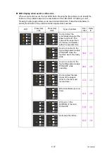
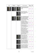
Page 35: ...polygon motor for the laser unit second time 2 33 050F 0305 Cannot detect the lock signal of the polygon motor for the laser unit first time 2 33 0800 0401 BD sensor failure second time 2 34 0900 Detected irregular power supply for more than 100 times 2 36 0402 0A01 0405 BD sensor failure first time 2 34 0A02 Detected a fan failure 2 36 0501 The center thermistor of the fuser unit has not reached ...

Page 36: ...01 2803 1A01 2804 1B01 2805 1C00 2806 1D01 2901 1D02 2902 1D03 2903 1D04 2904 1E01 2905 1E02 2906 1F00 2A01 1F02 2A02 2000 2A03 2001 2A04 2002 2A05 2003 2B01 2100 2B02 2101 2C01 2102 2C02 2103 2D01 2200 Cartridge sensor detected that the incompatible toner cartridge was installed 2 37 2E00 Could not communicate with the cartridge sensor on the machine side 2 37 2201 2E01 2202 2E03 2203 2F01 2400 T...

Page 37: ...01 Dot count or develop roller counter of the toner cartridge in models without toner box is reaching the upper limit in the continuous printing mode 2 38 3A00 A communication error occurred between the controller and engine in main PCB 2 37 4E01 Toner cartridge in models without toner box has reached the upper limit in the continuous printing mode 2 38 4000 Number of the drum unit rotations reach...

Page 38: ...ld not detect the new toner box correctly 2 39 6B03 6001 The front cover sensor detected that the front cover was open 2 40 6B04 6002 6B0A 6003 6C01 6004 The eject sensor detected that the fuser cover was open 2 40 6C02 6007 6C03 6101 The new toner sensor detected that no toner cartridge was set 2 41 6C04 6102 6D00 6103 6E00 6104 6F00 Detected that supply power is unstable less than 100 times 2 44...

Page 39: ...6 8503 7400 8504 7401 8505 7402 8506 7500 8507 7501 8508 7502 8601 7601 8602 7602 8603 7701 8604 7702 8701 7800 After the first side is printed in 2 sided printing mode the registration front sensor does not detect paper pass after a set period of time 2 46 8702 7801 8703 7802 8708 7803 8709 7804 870A 7805 870B 7900 870C 7A01 870D 7A02 870E 7B01 870F 7B02 8801 7B03 8802 7B04 8808 7B05 8809 7C00 88...

Page 40: ... printing 2 50 9001 The size of paper loaded in the MP tray and the one specified from the driver are not same when paper is fed from the MP tray 2 48 930A 9002 The size of paper loaded in the paper tray and the one specified from the driver are not same when paper is fed from the paper tray 2 48 9501 9003 9502 9004 9503 9005 9504 9006 9505 9102 9601 9103 9608 9104 9701 For 2 sided printing paper ...

Page 41: ...e memory size for secure print data 2 51 9C01 C900 9C02 CA00 9C03 D100 9C06 D200 9C07 D800 9D02 D900 9D03 DA00 9D04 DB00 9D05 E000 An error occurred in the ROM check sum 2 51 A000 E001 A200 E002 A300 E100 Program error 2 51 A400 E400 A500 E500 An error occurred during access to the DRAM in the main PCB ASSY 2 51 A600 E600 Write error in the EEPROM of the main PCB ASSY 2 51 A700 E701 A800 E702 Read...

Page 42: ...2 20 Confidential Error Codes Description Refer to Error Codes Description Refer to FA01 FB0A FA02 FB0B FA03 FB0C FB01 FB0D FB02 FB0E FB03 FB0F FB04 FC01 FB05 FC02 FB06 FC03 FB07 FC04 FB08 FC05 FB09 ...

Page 43: ... The side thermistor detected a temperature higher than the specified value 6801 2 43 Cover is Open Close the Front Cover The front cover sensor detected that the front cover was open 6001 2 40 Close the Fuser Cover which can be found behind the Back Cover of the machine The eject sensor detected that the fuser cover was open 6004 2 40 Drum Slide the Green tab on Drum Unit Electric discharge that ...

Page 44: ...fied time after the T1 paper feed sensor detected paper pass 7302 2 46 Machine Error F9 The spec code was not entered correctly F900 2 52 Manual Feed Load S paper There is no paper set in the manual feed slot on the manual feed slot printing 8C00 2 48 Media Mismatch Reload correct paper in MP Tray then press Go When printing from the MP tray paper type setting in the machine does not match the set...

Page 45: ...Low T1 Detected that the paper is running out when the paper feed motor drive and T1 paper empty sensor turned ON 4 11 3 Print Data Full Print Data is full Press Cancel and delete the previously stored data The memory used to store secure print data exceeded the memory size for secure print data C800 2 51 Print Unable 01 Turn the power off and then back on again ASIC error or motor driver error oc...

Page 46: ... when the machine was in the ready state 0B02 2 37 Print Unable 2E Turn the power off and then back on again Could not communicate with the cartridge sensor on the machine side 2E00 2 37 Print Unable 3A Turn the power off and then back on again A communication error occurred between the controller and engine in main PCB 3A00 2 37 Print Unable E0 Turn the power off and then back on again An error o...

Page 47: ...pper limit 4C06 2 38 Open the Front Cover replace Toner Cartridge Dot count or develop roller counter of the toner cartridge in models without toner box has reached the upper limit in the toner stop mode 4C01 2 38 Self Diagnostic Turn the power off then on again Leave the machine for 15 min Some fuser unit errors occurred at power ON or upon recovery from sleep mode 6901 2 43 Will Automatically Re...

Page 48: ...he paper tray 9002 2 48 Toner Ended Open the Front Cover replace Toner Cartridge Toner cartridge in models without toner box has reached the upper limit in the continuous printing mode 4E01 2 38 Toner Low Dot counter of the toner cartridge or develop roller counter reaches the upper limit soon 4B01 2 38 The amount of toner supplied of the toner box reaches the upper limit soon 4B06 2 38 Wrong Tone...

Page 49: ...ot detect paper pass after a set period of time 7800 2 46 The back cover sensor detected the open state when 2 sided printing is started before the registration of printing in the engine 8903 2 47 The back cover sensor detected the open state during 2 sided printing after the registration of printing in the engine 8904 2 47 The registration rear sensor detected that the paper fed was smaller or la...

Page 50: ...ched the upper limit in the continuous printing mode 4E01 2 38 Electric discharge that may be caused by dirt on the corona wire of the drum unit was detected 6A00 2 44 Number of the drum unit rotations reaches the upper limit soon 4000 2 38 Number of the drum unit rotations has reached the upper limit 4200 2 38 There is no paper set in the manual feed slot on the manual feed slot printing 8C00 2 4...

Page 51: ... detect the new drum unit correctly 4F05 2 39 New toner box sensor could not detect the new toner box correctly 5E00 2 39 The new toner sensor detected that no toner cartridge was set 6101 2 41 An error occurred in the ROM check sum E000 2 51 Program error E100 2 51 An error occurred during access to the DRAM in the main PCB ASSY E500 2 51 Read error in the flash ROM E702 2 51 The side thermistor ...

Page 52: ... stabilize within the specified time 0201 2 33 An error occurred in the high voltage power supply PCB ASSY when the machine was in the ready state 0B02 2 37 An error occurred in the high voltage power supply PCB ASSY while operating 0B01 2 37 Cannot detect the lock signal of the polygon motor for the laser unit second time 0300 2 33 BD sensor failure second time 0401 2 34 Write error in the EEPROM...

Page 53: ...being checked If power is turned OFF and ON after error code 6901 occurred this code is displayed for about 15 minutes 6902 2 43 After the heat unit was heated normally the center thermistor of the fuser unit detected a temperature lower than the specified value 0504 2 35 The center thermistor of the fuser unit detected a temperature rise greater than the specified value within the specified time ...

Page 54: ... the specified time 0501 2 35 The center thermistor of the fuser unit detected a temperature higher than the specified value 0503 2 35 ASIC error or motor driver error occurred 0102 2 33 Could not communicate with the cartridge sensor on the machine side 2E00 2 37 A communication error occurred between the controller and engine in main PCB 3A00 2 37 LED Press Go once Press Go twice Type of problem...

Page 55: ...SY Step Cause Remedy 1 Connection failure of the paper feed motor flat cable Reconnect the paper feed motor flat cable 2 Connection failure of the low voltage power supply PCB harness Reconnect the low voltage power supply PCB harness 3 Paper feed motor flat cable failure Replace the paper feed motor flat cable 4 Damaged parts in main drive Replace the frame L unit 5 Damaged fuser unit Replace the...

Page 56: ...nsation Leave the front and back cover open for at least 30 minutes when the power is ON Close those covers and turn the power switch OFF and then back ON again Step Cause Remedy 1 Connection failure of the laser unit flat cable Reconnect the laser unit flat cable 2 Laser unit failure Replace the laser unit 3 Main PCB failure Replace the main PCB ASSY ...

Page 57: ...er thermistor or the side thermistor of the fuser unit Error code 050B When the center thermistor of the fuser unit was lower than the idle temperature the side thermistor detected a temperature higher than the specified temperature Error code 050C When the center thermistor of the fuser unit was higher than the idle temperature the side thermistor detected a temperature lower than the specified t...

Page 58: ... Error code 0900 of the low voltage power supply PCB occurs when there is a large distortion in the power supply voltage supplied to the machine In this case if the same power supply is used the same error might occur again even if the low voltage power supply PCB ASSY is replaced For this reason be sure to ask the user to rearrange the installation environment Step Cause Remedy 1 Connection failu...

Page 59: ...ge could not communicate with the cartridge sensor Error code 2E00 Could not communicate with the cartridge sensor on the machine side User Check Replace with a toner cartridge which has a correspondent capacity Error code 3A00 A communication error occurred between the controller and engine in main PCB Step Cause Remedy 1 Dirt on the machine the drum unit the toner cartridge and the toner box ter...

Page 60: ...op roller counter of the toner cartridge in models without toner box is reaching the upper limit in the continuous printing mode Error code 4E01 Toner cartridge in models without toner box has reached the upper limit in the continuous printing mode User Check Replace the toner cartridge whose counter reached the upper limit Step Cause Remedy 1 If the error display is not cleared after the drum uni...

Page 61: ...User Check Replace the toner box with a new toner box again If the machine is on the uneven surface place it on a level surface Step Cause Remedy 1 Connection failure of the new toner sensor PCB harness Reconnect the new toner sensor PCB harness 2 New toner actuator coming off or caught in some sections of the machine Reattach the new toner actuator 3 New toner sensor failure Replace the new toner...

Page 62: ...ensor harness 2 Front cover failure Replace the front cover 3 Front cover sensor failure Replace the front cover sensor 4 Main PCB failure Replace the main PCB ASSY Step Cause Remedy 1 Eject actuator coming off or caught in some sections of the machine Reattach the eject actuator 2 Fuser cover attachment failure Reattach the fuser cover 3 Connection failure of the eject sensor PCB harness Reconnec...

Page 63: ...wer supply PCB ASSY 3 Main PCB failure Replace the main PCB ASSY Step Cause Remedy 1 New toner box actuator coming off or caught in some sections of the machine Reattach the new toner box actuator 2 New toner box sensor failure Replace the high voltage power supply PCB ASSY 3 Main PCB failure Replace the main PCB ASSY Step Cause Remedy 1 Dirt on the electrodes of the drum unit and those of the mac...

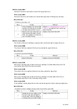
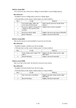
Page 64: ...2 42 Confidential Electrodes location of main body Fig 2 8 Electrodes location of the drum unit and process unit Fig 2 9 ...

Page 65: ...r harness 2 Fuser unit thermistor failure Replace the fuser unit 3 Main PCB failure Replace the main PCB ASSY Step Cause Remedy 1 Connection failure of a fuser unit harness Reconnect the fuser unit harness 2 Connection failure of the eject sensor PCB harness Reconnect the eject sensor PCB harness 3 Fuser unit failure Replace the fuser unit 4 Eject sensor PCB failure Replace the eject sensor PCB AS...

Page 66: ... 2 Dirt on the high voltage power supply PCB terminal Clean the high voltage power supply PCB terminal 3 High voltage power supply PCB failure Replace the high voltage power supply PCB ASSY 4 Main PCB failure Replace the main PCB ASSY Step Cause Remedy 1 The power supply waveform is incorrect Install a voltage stabilizer in the power supply part Step Cause Remedy 1 Foreign object inside the machin...

Page 67: ...some sections of the machine Reattach the eject actuator 3 Fuser cover attachment failure Reattach the fuser cover 4 Back cover attachment failure Reattach the back cover 5 Eject sensor failure Replace the eject sensor PCB ASSY 6 Back cover failure Replace the back cover 7 Damaged fuser drive gear 64R 36R Replace the fuser drive gear 64R 36R 8 Damaged gears in the paper feed drive system Replace t...

Page 68: ...achine Remove the foreign object 2 Registration front actuator attachment failure Reattach the registration front actuator 3 Connection failure of the registration front rear sensor harness Reconnect the registration front rear sensor harness 4 Registration front rear sensor PCB failure Replace the actuator holder ASSY 5 Damaged gears in the paper feed drive system Replace the frame L unit 6 Main ...

Page 69: ...e User Check Use appropriate paper Letter to Legal Step Cause Remedy 1 Duplex tray is not set correctly Reattach the duplex tray correctly 2 Back cover sensor attachment failure Reattach the back cover sensor 3 Breakage of boss that presses the back cover sensor Replace the back cover 4 Guide which pushes the back cover sensor of the duplex tray is faulty Replace the duplex tray 5 Back cover senso...

Page 70: ...ng from the paper tray paper type setting in the machine does not match the setting in the driver User Check Use the same paper type setting for the machine and driver Step Cause Remedy 1 Registration front actuator caught in some sections of the machine Reattach the registration front actuator 2 Connection failure of the registration front rear sensor PCB harness Reconnect the registration front ...

Page 71: ... paper empty sensor models only Reconnect the T1 paper empty paper feed sensor harness 2 Connection failure of the T1 clutch harness Reconnect the T1 clutch harness 3 Connection failure of the paper feed motor flat cable Reconnect the paper feed motor flat cable 4 T1 paper feed actuator caught in some sections of the machine non paper empty sensor models only Reattach the T1 paper feed actuator 5 ...

Page 72: ...n paper empty sensor models only Reconnect the T1 paper feed sensor harness 3 Connection failure of the T1 paper empty paper feed sensor harness paper empty sensor models only Reconnect the T1 paper empty paper feed sensor harness 4 Connection failure of the T1 clutch harness Reconnect the T1 clutch harness 5 T1 MP paper empty actuator caught in some sections of the machine Reattach the T1 MP pape...

Page 73: ...rmware Error code E500 An error occurred during access to the DRAM in the main PCB ASSY Error code E600 Write error in the EEPROM of the main PCB ASSY Error code E702 Read error in the flash ROM Error code E900 An error occurred while initializing the NFC Step Cause Remedy 1 Main PCB failure Replace the main PCB ASSY Step Cause Remedy 1 Main PCB failure Replace the main PCB ASSY Step Cause Remedy ...

Page 74: ...se Remedy 1 The power was turned OFF while function code 74 was running Reenter the spec code Refer to 1 3 16 Setting by spec Function code 74 in Chapter 5 2 Main PCB failure Replace the main PCB ASSY Memo Press the or the under error code F900 display to select the maintenance mode ...

Page 75: ... 3 Connection failure of the paper feed motor flat cable Reconnect the paper feed motor flat cable 4 Connection failure of the T1 paper feed sensor harness non paper empty sensor models only Reconnect the T1 paper feed sensor harness 5 Connection failure of the T1 clutch harness Reconnect the T1 clutch harness 6 Connection failure of the T1 paper empty paper feed sensor harness paper empty sensor ...

Page 76: ...whether the paper tray is closed correctly Step Cause Remedy 1 MP roller holder ASSY attachment failure Reattach the MP roller holder ASSY correctly 2 Connection failure of the paper feed motor flat cable Reconnect the paper feed motor flat cable 3 Connection failure of the MP paper empty registration front sensor harness Reconnect the MP paper empty registration front sensor harness 4 Paper feed ...

Page 77: ...0 to 230 g m2 for the MP tray Flip through the paper and reset it in the paper tray Step Cause Remedy 1 T1 roller holder ASSY attachment failure Reattach the T1 roller holder ASSY 2 Connection failure of the paper feed motor flat cable Reconnect the paper feed motor flat cable 3 Connection failure of the registration front rear sensor harness Reconnect the registration front rear sensor harness 4 ...

Page 78: ...t an angle User Check Check that the paper is set in each paper tray correctly Flip over the paper in each paper tray or rotate the paper 180 Adjust each paper guide according to each paper size Check that the thickness of the paper is 60 to 163 g m2 for the paper tray and 60 to 230 g m2 for the MP tray Check that there is not too much paper set in the paper tray Check that the type of paper is ap...

Page 79: ...se the back cover completely Close the paper tray completely Set the driver setting to duplex printing Use A4 or Letter paper specified by the manufacturer Step Cause Remedy 1 Fuser unit failure Replace the fuser unit 2 Main PCB failure Replace the main PCB ASSY Step Cause Remedy 1 Eject actuator coming off Reattach the eject actuator 2 Back cover failure Replace the back cover 3 Eject sensor fail...

Page 80: ...nsor harness Reconnect the registration front rear sensor harness 6 Connection failure of the registration clutch harness Reconnect the registration clutch harness 7 Connection failure of the T1 paper feed sensor harness non paper empty sensor models only Reconnect the T1 paper feed sensor harness 8 Connection failure of the T1 paper empty paper feed sensor harness paper empty sensor models only R...

Page 81: ...ign object around the MP tray Remove the foreign object 2 Connection failure of the MP paper empty registration front sensor harness Reconnect the MP paper empty registration front sensor harness 3 MP registration front actuator coming off Reattach the MP registration front actuator 4 Connection failure of the registration clutch harness Reconnect the registration clutch harness 5 Paper feed motor...

Page 82: ... the registration front rear sensor harness Reconnect the registration front rear sensor harness 3 T1 registration front actuator coming off Reattach the T1 registration front actuator 4 Connection failure of the registration clutch harness Reconnect the registration clutch harness 5 Registration front rear sensor failure Replace the actuator holder ASSY 6 Paper feed motor failure Replace the pape...

Page 83: ...eplace the drum unit Step Cause Remedy 1 Foreign object inside the machine Remove the foreign object 2 Eject actuator coming off Reattach the eject actuator 3 Connection failure of the eject sensor harness Reconnect the eject sensor harness 4 Fuser cover attachment failure Reattach the fuser cover 5 Damaged fuser drive gear Replace the fuser drive gear 6 Eject sensor failure Replace the eject sens...

Page 84: ...urer Check that the paper size is matched to the setting for the duplex printer Step Cause Remedy 1 Foreign object in the rear of the machine Remove the foreign object 2 Eject actuator coming off Reattach the eject actuator 3 Connection failure of the eject sensor harness Reconnect the eject sensor harness 4 Fuser cover attachment failure Reattach the fuser cover 5 Eject sensor failure Replace the...

Page 85: ...etely blank 2 67 Image distortion 2 67 All black 2 68 Dirt on back side of paper 2 68 Vertical streaks 2 69 Horizontal stripes 2 70 White vertical streaks on image 2 70 Faint print 2 71 White spots on image 2 72 Band 2 74 Downward fogging of solid color 2 76 Horizontal lines 2 76 Ghost 2 77 Fogging 2 77 White horizontal stripes on image 2 71 Spots or dirt 2 73 ...

Page 86: ...er switch and leave the machine for a while condensation Check if paper is not damp Use specified paper Step Cause Remedy 1 Dirt on the electrodes of the drum unit and those of the machine Clean the electrodes of the drum unit and those of the machine Refer to Fig 2 8 P2 42 and Fig 2 9 P2 42 2 Dirt on the electrodes of the toner cartridge and those of the machine Clean the electrodes of the toner ...

Page 87: ...er Check Check whether appropriate paper type is selected on the driver Install the latest main firmware Step Cause Remedy 1 Registration rear actuator coming off Reattach the registration rear actuator 2 Laser unit failure Replace the laser unit 3 Main PCB failure Replace the main PCB ASSY ...

Page 88: ...ailure Replace the fuser unit 5 High voltage power supply PCB failure Replace the high voltage power supply PCB ASSY 6 Laser unit failure Replace the laser unit 7 Main PCB failure Replace the main PCB ASSY User Check Check the usage environment of the machine Using the machine in hot humid or cold dry conditions can cause this problem Clean the corona wire of the drum unit Replace the drum unit wi...

Page 89: ... Reattach the laser unit 3 Laser unit flat cable failure Replace the laser unit flat cable 4 Dirt on the electrodes of the high voltage power supply PCB and those of the machine Clean the electrodes of the high voltage power supply PCB and those of the machine 5 Laser unit failure Replace the laser unit 6 Main PCB failure Replace the main PCB ASSY Step Cause Remedy 1 Laser unit attachment failure ...

Page 90: ...e high voltage power supply PCB and those of the machine Clean the electrodes of the high voltage power supply PCB and those of the machine 4 High voltage power supply PCB failure Replace the high voltage power supply PCB ASSY 5 Laser unit failure Replace the laser unit 6 Main PCB failure Replace the main PCB ASSY User Check This problem may disappear after printing multiple sheets of paper Replac...

Page 91: ...emedy 1 Dirt in the paper feed system Wipe dirt off 2 A ground wire or ground plate installation failure Grounding is not performed correctly Retighten the screws of each ground wire or ground plate Repair the bend of the tray ground spring of the paper tray Refer to the figure below 3 Dirt on the exposure drum Perform drum cleaning Refer to 2 2 Drum Cleaning in Chapter 5 4 Dirt on the cleaner pin...

Page 92: ...A ground wire or ground plate installation failure Grounding is not performed correctly Retighten the screws of each ground wire or ground plate Repair the bend of the tray ground spring of the paper tray Refer to Fig 2 14 P2 69 4 Scratch or dirt on the fuser unit Replace the fuser unit 5 High voltage power supply PCB failure Replace the high voltage power supply PCB ASSY User Check Check that the...

Page 93: ... and Fig 2 8 P2 42 2 Dirt on the exposure drum Perform drum cleaning Refer to 2 2 Drum Cleaning in Chapter 5 3 Scratch or dirt on the fuser unit Replace the fuser unit 4 High voltage power supply PCB failure Replace the high voltage power supply PCB ASSY User Check Check that the machine is positioned on a level surface Replace the drum unit with a new one Replace the toner cartridge with a new on...

Page 94: ... drum Perform drum cleaning Refer to 2 2 Drum Cleaning in Chapter 5 3 Clogged filter Clean the filter 4 Scratch or dirt on the fuser unit Replace the fuser unit 5 High voltage power supply PCB failure Replace the high voltage power supply PCB ASSY Note Image defects which appear periodically may be caused by failure of rollers Refer to the table below and determine the cause based on the pitch at ...

Page 95: ... to the Fig 2 10 P2 53 to clean the paper dust cleaning roller 2 Dirt on the exposure drum Perform drum cleaning Refer to 2 2 Drum Cleaning in Chapter 5 3 Clogged filter Clean the filter 4 Scratch or dirt on the fuser unit Replace the fuser unit 5 High voltage power supply PCB failure Replace the high voltage power supply PCB ASSY Note Image defects which appear periodically may be caused by failu...

Page 96: ...sappear after printing multiple sheets of paper Refer to How to clean the drum unit to remove the dirt from the exposure drum using a cotton applicator Replace the drum unit with a new one Replace the toner cartridge with a new one Step Cause Remedy 1 A ground wire or ground plate installation failure Grounding is not performed correctly Retighten the screws of each ground wire or ground plate Rep...

Page 97: ...ere is a mark in drum region 2 Fig 2 17 3 Turn the edge of the drum unit towards you while looking at the drum surface to find the mark Fig 2 18 4 Wipe the surface of the drum gently with a dry cotton swab until the mark or foreign material on the surface comes off Fig 2 19 Note Do not clean the exposure drum surface with anything sharp like a ball pointed pen ...

Page 98: ... How to clean the drum unit to remove the dirt from the exposure drum using a cotton applicator Replace the drum unit with a new one Replace the toner cartridge with a new one Step Cause Remedy 1 Dirty charge electrodes Clean the electrodes of the drum unit and those of the machine Refer to Fig 2 9 P2 42 and Fig 2 8 P2 42 2 Dirt on the exposure drum Perform drum cleaning Refer to 2 2 Drum Cleaning...

Page 99: ...ck Check the usage environment of the machine Using the machine in hot humid or cold dry conditions can cause this problem Check if the acid paper is not used This problem may disappear after printing multiple sheets of paper Replace the toner cartridge with a new one Replace the drum unit with a new one Step Cause Remedy 1 Dirt on the electrodes of the toner cartridge and those of the machine Cle...

Page 100: ... to verify the product ID in Macintosh 1 Select About This Mac from the Apple menu 2 Click the More Info in the About This Mac dialog box 3 Select USB under the Hardware in Contents on the left side 4 Select the machine HL XXXX from USB Device Tree 5 Check Product ID in HL XXXX Product ID Hexadecimal HL 2290 0093h HL L2310D 009Ah HL 2295D 0094h HL L2312D 009Ah HL 2590DN 0095h HL L2310DR 009Ah HL 2...

Page 101: ...oint User Check Check the wireless LAN settings Check the access point settings Change the machine installation location Set the access point manually Step Cause Remedy 1 Connection failure of the wireless LAN PCB connector Reconnect the wireless LAN PCB connector 2 Wireless LAN PCB failure Replace the wireless LAN PCB 3 LAN terminal pin deformation Main PCB failure Replace the main PCB ASSY Step ...

Page 102: ...e Reconnect the LCD relay flat cable 5 Panel relay PCB failure Replace the panel relay PCB ASSY 6 LCD failure Replace the LCD panel ASSY 7 Low voltage power supply PCB failure Replace the low voltage power supply PCB ASSY 8 Main PCB failure Replace the main PCB ASSY Step Cause Remedy 1 Connection failure of the panel flat cable Reconnect the panel flat cable 2 Panel PCB failure Replace the panel P...

Page 103: ...ith toner box Reconnect the new toner box sensor PCB harness 4 Connection failure of the toner box relay PCB harness Models with toner box Reconnect the toner box relay PCB harness 5 New toner sensor PCB failure Models without toner box Replace the new toner sensor PCB ASSY 6 New toner box sensor PCB failure Models with toner box Replace the new toner box sensor PCB ASSY 7 Relay PCB failure Models...

Page 104: ...odels with toner box Reconnect the toner box relay PCB harness 5 New toner sensor PCB failure Models without toner box Replace the new toner sensor PCB ASSY 6 New toner box sensor PCB failure Models with toner box Replace the new toner box sensor PCB ASSY 7 Relay PCB failure Models with toner box Replace the relay PCB ASSY 8 High voltage power supply PCB failure Replace the high voltage power supp...

Page 105: ...lace the eject sensor PCB ASSY 6 Low voltage power supply PCB failure Replace the low voltage power supply PCB ASSY 7 Fuser unit failure Replace the fuser unit 8 Main PCB failure Replace the main PCB ASSY Note Turn the power switch OFF and then ON again Leave the machine for 15 minutes This problem may then be cleared The machine may recover from the error when the test printing of the maintenance...

Page 106: ...N again Install the latest main firmware Check the print limit ID Check that the print data is not damaged 4 10 2Full memory User Check Print the accumulated data Reduce the amount or resolution of the data Step Cause Remedy 1 Main PCB failure Replace the main PCB ASSY Step Cause Remedy 1 Main PCB failure Replace the main PCB ASSY ...

Page 107: ...the MP paper empty sensor PCB harness 3 Connection failure of the T1 paper feed sensor harness non paper empty sensor models only Reconnect the T1 paper feed sensor harness 4 Connection failure of the T1 paper empty paper feed sensor harness paper empty sensor models only Reconnect the T1 paper empty paper feed sensor harness 5 Connection failure of the T1 clutch harness Reconnect the T1 clutch ha...

Page 108: ...e and main firmware in this order 2 In case of update failure by interruption the firmware might not correctly written in the ROM Update the firmware again by the following procedure 1 Turn OFF the machine 2 For LED models Open the front cover and then turn ON the machine while pressing the Go If the Paper Drum and Toner LEDs light release the Go If all LEDs go out press the Go four times For LCD ...

Page 109: ...arness non paper empty sensor models only Reconnect the T1 paper feed sensor harness 2 Connection failure of the T1 paper empty paper feed sensor harness paper empty sensor models only Reconnect the T1 paper empty paper feed sensor harness 3 T1 paper feed sensor PCB failure non paper empty sensor models only Replace the T1 paper feed sensor PCB ASSY 4 T1 paper empty paper feed sensor PCB failure p...

Page 110: ...k that the cables are not at an angle When connecting or disconnecting harnesses hold the connector body not the cables If the connector is locked release it first After a repair check not only the repaired portion but also harness treatment Also check that other related portions are functioning properly Forcefully closing the front cover without mounting the toner cartridge and the drum unit can ...

Page 111: ...3 2 Confidential 2 PACKING Fig 3 1 Option carton Carton Polystyrene pad ASSY Spacer carton Process pad Carton Bag Bag Polystyrene pad ASSY AC cord carton Process pad ...

Page 112: ...2DB Taptite bind B M3x8 Taptite bind B M3x10 Taptite bind B M4x12 Screw cup M3x8 Taptite cup S M3x6 SR Taptite cup S M3x8 SR Taptite cup S Screw cup Taptite pan B Taptite bind B Taptite pan B M4x14 Screw pan Screw pan S P washer Screw bind Screw bind M3x4 Screw pan M4x8 ...

Page 113: ...G plate 1 Screw cup M3x8 black 2 0 6 0 1 6 1 Main PCB ASSY Screw cup M3x8 black 3 0 6 0 1 6 1 MP frame parts For MP models Taptite bind B M4x12 3 0 8 0 1 8 1 Taptite pan B M4x14 1 0 8 0 1 8 1 Front chute ASSY For manual feed models Taptite bind B M4x12 2 0 8 0 1 8 1 Screw pan S P washer M3x12DB 1 0 5 0 1 5 1 For MP models Taptite bind B M4x12 3 0 8 0 1 8 1 Frame L unit Taptite bind B M4x12 11a Und...

Page 114: ... 0 1 8 1 Main shield plate Taptite cup S M3x8 SR 1 0 5 0 1 5 1 Screw pan S P washer M3x12DB 1 0 5 0 1 5 1 LVPS shield plate Taptite cup S M3x8 SR 1 0 55 0 05 5 5 0 5 Taptite bind B M4x12 1 0 8 0 1 8 1 Frame R unit Taptite cup S M3x6 SR 1 0 5 0 1 5 1 Taptite bind B M4x12 2 0 8 0 1 8 1 Registration front rear actuator holder ASSY Taptite bind B M3x10 1 0 5 0 1 5 1 Location of screw Screw type Q ty T...

Page 115: ... Confidential 5 LUBRICATION Fuser gear 64R 36R Fig 3 3 Lubricating oil type Maker name Lubrication point Quantity of lubrication FLOIL BG 10KS Kanto Kasei Fuser gear 64R 36R 3 places 1 5 to 2 0 mm dia ball ...

Page 116: ...ars come off 1 D00AHW Ejector gear 16 15 8 D00HHK Gear 70R DEV 2 LY9006 Ejector gear 33 9 D00HHM Clutch DEV NON toner box 3 LY9005 Ejector gear 40 10 D00HHL Gear 55 DEV 4 D00ALK Gear oneway 35L 22 fuser 11 D00EFZ Gear DEV idle 24 5 D00ALM Clutch fuser 12 D00AKE Gear 115L 30L drum 6 D00ALL Gear oneway 20 fuser 13 D00AH4 Gear 47R DX 7 D00ALH Gear 64R 36R fuser 1 2 3 7 4 5 6 8 9 10 12 13 11 1 2 3 5 4...

Page 117: ...that frame L faces up Otherwise all gears come off 14 D00EGI Gear toner box idle 32 19 D00CXT Gear 23R PF 15 D00CUB Sector gear toner box 20 D00AK9 Gear 38L PF 16 D00AM4 Gear 68R drum idle 21 D00AK8 Gear 28R 18 PF 17 D00AKA Gear 50L PF 22 D00AK7 Gear 34L PF 18 D00CXU Clutch PF 23 LY9088 Feeder gear 34 17 18 19 16 15 14 20 21 22 23 17 16 15 14 18 19 20 21 23 22 ...

Page 118: ...fidential 7 HARNESS ROUTING 1 Top cover ASSY Harness colors are subject to change for some reason LCD models LCD flat cable Panel flat cable Panel flat cable LED models NFC flat cable Only for models with NFC ...

Page 119: ... Center thermistor harness ASSY WH LVPS heater harness BK WH Fuser unit heater harness WH Fan harness RD BK WH New toner sensor flat cable HVPS flat cable Polygon motor harness WH High voltage power supply PCB ASSY Eject sensor PCB ASSY Ground harness GR YW Laser unit flat cable Registration front rear sensor harness GR WH BL RD ...

Page 120: ...p side of the machine Harness colors are subject to change for some reason HVPS flat cable Main PCB ASSY Polygon motor harness WH Toner box relay flat cable 1 MP relay flat cable 2 1 For models with Toner box 2 For MP models ...

Page 121: ...rness BL Registration clutch harness WH Polygon motor harness WH LVPS harness WH BK Paper feed motor flat cable Registration clutch Paper feed sensor harness RD BL WH Eject sensor flat cable Main PCB ASSY Panel flat cable Cartridge sensor harness WH 2 Toner box solenoid harness WH 1 Toner box new harness BL 1 Relay PCB ASSY 1 Toner sensor harness RD 1 1 For models with Toner box 2 For models witho...

Page 122: ...Back cover duplex tray sensor harness RD BL T1 clutch harness BL Registration clutch harness WH Polygon motor harness WH LVPS harness WH BK Paper feed motor flat cable Registration clutch Paper feed sensor harness WH Eject sensor flat cable Main PCB ASSY Panel flat cable Relay PCB ASSY MP sensor harness BK MP paper empty sensor harness RD NFC flat cable MP relay flat cable ...

Page 123: ...e registration chute Harness colors are subject to change for some reason Registration front rear sensor harness GR WH BL RD Paper feed sensor harness RD BL WH Paper feed sensor harness RD BL WH LVPS harness WH BK Top side Frame R unit ...

Page 124: ...3 15 Confidential 7 Frame R unit Harness colors are subject to change for some reason Registration front rear sensor harness GR WH BL RD LVPS harness WH BK ...

Page 125: ...9 13 HVPS flat cable High voltage power supply PCB ASSY 10 25 9 12 New toner sensor PCB ASSY 5 5 9 16 Laser unit flat cable Laser unit 15 30 9 8 Side cover L 10 10 9 27 Eject sensor PCB ASSY 25 30 9 9 Panel flat cable LCD ASSY NFC PCB ASSY 4 10 10 9 28 Registration front rear actuator holder ASSY 50 60 9 29 Paper feed roller ASSY Paper feed sensor PCB ASSY 25 30 9 24 Fuser gear 64R 36R 5 5 9 25 To...

Page 126: ...th the disassembly procedure 1 Disconnect the following USB cable if connected LAN cable if connected 2 Remove the following Paper tray Toner cartridge Drum unit or Toner box Process unit Duplex tray LAN port cap Fig 3 8 Duplex tray LAN port cap USB cable LAN cable Paper tray Toner cartridge Drum unit or Toner box Process unit ...

Page 127: ...ver outward and remove the Pin on the Outer chute ASSY 3 Pull out the right side of the Back cover in the direction of the arrow A to remove it from the Boss and remove the Back cover in the direction of the arrow B Fig 3 9 Boss Back cover Back cover Pin Rib A Outer chute ASSY Rib B Boss ...

Page 128: ...ute ASSY 1 Pull out the right side of the Outer chute ASSY in the direction of the arrow A to remove the Boss of the Outer chute ASSY and remove the Outer chute ASSY in the direction of the arrow B Fig 3 10 Boss Outer chute ASSY A B ...

Page 129: ...r 4 to remove the Develop joint link from the Front cover ASSY 3 Lift the Rib on the Front chute ASSY and slide the Front cover ASSY in the direction of the arrow A to remove it 4 Remove the Support flap from the Front cover ASSY Fig 3 11 Rib Front chute ASSY Develop joint link Front cover ASSY Collar 4 A Support flap ...

Page 130: ...nt cover ASSY Open the MP tray and release each Boss and remove the MP paper guide from the MP tray 3 Pull out the Link MP pin to remove the Develop joint link MP from the Front cover ASSY Fig 3 13 Front cover ASSY Collar 5 Link MP pin MP tray Front cover ASSY Develop joint link MP Link MP pin Bosses MP paper guide Bosses ...

Page 131: ...3 22 Confidential 4 Open the Front cover ASSY Release each Boss and remove the Front cover ASSY 5 Remove the Support flap from the Front cover ASSY Fig 3 14 Boss Front cover ASSY Support flap Boss ...

Page 132: ...3 23 Confidential 9 5 Side cover R 1 Release the Hooks A B and the Hook C on the Side cover R in order of the arrow A to C and remove the Side cover R Fig 3 15 Hook C Hooks B Side cover R Hooks A C B A ...

Page 133: ...the Knobs on the Fuser cover and pull the Fuser cover down 2 Pull the Fuser cover in the direction of the arrow to remove it from the Bosses and remove the Fuser cover Fig 3 16 Boss Fuser cover Knob Fuser cover Knob Fuser cover Boss Boss Boss ...

Page 134: ...3 17 Assembling Note When attaching the Inner chute ASSY engage the Hooks on the Inner chute ASSY with the Positioning holes on the Top cover ASSY After assembling the Inner chute ASSY pull up the Green envelope levers on both sides of the Fuser unit Fuser unit Hooks Green envelope lever Taptite bind B M4x12 Inner chute ASSY Green envelope lever Fuser unit Positioning holes Top cover ASSY ...

Page 135: ...3 26 Confidential 9 8 Side cover L 1 Release the Hooks A B and the Hook C on the Side cover L in order of the arrow A to C and remove the Side cover L Fig 3 18 Hooks A Hooks B Side cover L Hook C C B A ...

Page 136: ... arrow 4 Remove the Paper stopper from the Top cover ASSY Fig 3 19 Note After disconnecting flat cables check that each cable is not damaged at its end or short circuited When connecting flat cables do not insert them at an angle After insertion check that the cables are not at an angle Top cover ASSY Hook A Panel flat cable Taptite bind B M4x12 Main PCB ASSY Hook C Hook D Hook B Panel flat cable ...

Page 137: ...e each Hook to remove the Panel PCB ASSY from the Top cover ASSY Release the Panel flat cable from the securing fixtures Fig 3 20 Harness routing Refer to 1 Top cover ASSY Panel flat cable Panel PCB ASSY Top cover ASSY Bottom side of Top cover ASSY Hooks ...

Page 138: ...from the securing fixtures Fig 3 21 Harness routing Refer to 1 Top cover ASSY Note After disconnecting flat cables check that each cable is not damaged at its end or short circuited When connecting flat cables do not insert them at an angle After insertion check that the cables are not at an angle Panel flat cable LCD flat cable Top cover ASSY LCD PCB ASSY Hooks Hooks Bottom side of Top cover ASSY...

Page 139: ...r ASSY 9 Release the Hook B to remove the LCD ASSY from the LCD cover 10 Release the Hook C to remove the NFC PCB ASSY from the Top cover ASSY Only for models with NFC Fig 3 22 LCD cover Hole Top cover ASSY Hooks A Hook B LCD ASSY LCD flat cable Rubber key NFC PCB ASSY Only for models with NFC Hook C Bottom side of Top cover ASSY ...

Page 140: ...t the Center thermistor harness ASSY and the Side thermistor harness ASSY from the Eject sensor PCB ASSY 3 Release the Center thermistor harness ASSY and the Side thermistor harness ASSY from the securing fixtures Fig 3 24 Harness routing Refer to 2 Rear side of the machine LVPS heater harness Fuser unit heater harness Back side Side thermistor harness ASSY Center thermistor harness ASSY Eject sen...

Page 141: ... B M4x14 screws and remove the Fuser unit Fig 3 25 Fig 3 26 Note DO NOT apply a physical impact or vibration to the Fuser unit DO NOT touch the roller and the electrodes to prevent breakage of the Fuser unit Taptite pan B M4x14 Fuser unit Back side ...

Page 142: ...g the Low voltage power supply DO NOT touch it within 3 minutes after disconnecting the AC cord as it may cause an electric shock due to the electric charge accumulated in the capacitor Assembling Note Make sure to attach the LVPS insulation sheet Failure to attach the insulation sheet can result in fire or electrical shock Screw pan M4x8 Screw cup M3x8 black LVPS insulation sheet LVPS shield plat...

Page 143: ...wer supply PCB ASSY Disconnect the LVPS harness from the back of the Low voltage power supply PCB ASSY Fig 3 28 Harness routing Refer to 2 Rear side of the machine Assembling Note After the replacement refer to 2 IF YOU REPLACE THE LOW VOLTAGE POWER SUPPLY PCB ASSY in Chapter 4 to reset irregular power supply detection counter of the Low voltage power supply PCB ASSY LVPS shield plate LVPS harness...

Page 144: ...ease the Hook to remove the New toner sensor PCB ASSY Disconnect the Registration front rear sensor harness from the New toner sensor PCB ASSY Fig 3 29 Harness routing Refer to 2 Rear side of the machine New toner sensor flat cable Hook Registration front rear sensor harness Front side New toner sensor PCB ASSY High voltage power supply PCB ASSY ...

Page 145: ... High voltage power supply PCB ASSY in the direction of the arrow B to remove it from the Rib Fig 3 30 Harness routing Refer to 2 Rear side of the machine and 3 Top side of the machine Note After disconnecting flat cables check that each cable is not damaged at its end or short circuited When connecting flat cables do not insert them at an angle After insertion check that the cables are not at an ...

Page 146: ...ssembling Note Fold the HVPS flat cable at the positions described below Electrode 20 Mountain fold Valley fold Reinforcing tape 45 20 45 Main PCB side High voltage power supply PCB side 45 38 1 81 1 191 1 536 10 224 1 89 1 116 1 ...

Page 147: ... out the Fan harness from the Hole Fig 3 32 Harness routing Refer to 2 Rear side of the machine Assembling Note When assembling the Fan insert the Fan harness into the hole to make sure that the Fan harness is not caught Attach the Fan so that the surface with the Label faces out Fan harness Label Hook Fan Hole Back side Hook ...

Page 148: ...he Taptite bind B M3x8 screw to remove the Shading film and the Toner box new PCB ASSY Fig 3 33 Harness routing Refer to 3 Top side of the machine and 4 Frame L unit Manual feed models Assembling Note Secure each harness in the Hooks in order of the Hook A to D and then secure them in the Hooks from the Hook E to F Be sure to give them enough slack in the G part for adjustment Taptite bind B M4x12...

Page 149: ...elay PCB ASSY Fig 3 34 Harness routing Refer to 3 Top side of the machine and 5 Frame L unit MP models Assembling Note Secure each harness in the Hooks in order of the Hook A to E and then secure them in the Hooks from the Hook F to G Be sure to give them enough slack in the H part for adjustment Taptite bind B M4x12 Relay PCB ASSY MP relay flat cable Main PCB ASSY MP sensor harness MP paper empty...

Page 150: ...te cup S M3x8 SR screws to remove the Laser unit Fig 3 35 Harness routing Refer to 3 Top side of the machine 4 Frame L unit Manual feed models Note After disconnecting flat cables check that each cable is not damaged at its end or short circuited When connecting flat cables do not insert them at an angle After insertion check that the cables are not at an angle Taptite cup S M3x8 SR Main PCB ASSY ...

Page 151: ...te After the replacement refer to 3 IF YOU REPLACE THE LASER UNIT in Chapter 4 to enter the adjusted value of the Laser unit Assembling Note Attach the laser serial number label as shown in the figure above on the Scanner plate after replacing the Laser unit 45 Main PCB side 71 1 108 1 234 5 Mountain fold Valley fold Laser unit side Electrode Electrode Laser serial number label Laser unit Scanner ...

Page 152: ...3 43 Confidential 9 17 Filter 1 Release the Hook to remove the Filter from the Air duct Fig 3 38 Hook Filter Air duct ...

Page 153: ... LAN PCB to the Hole on the machine and connect the Wireless LAN PCB to the Main PCB ASSY When assembling the Wireless LAN PCB remove all the tapes on the Wireless LAN PCB Also do not attach a tape These tapes are for securing the Wireless LAN PCB during the shipping not required for usage These tapes are special tape and using other tapes may cause short circuit between terminals Main PCB ASSY Ho...

Page 154: ...irection of the arrow A Rotate the Roller holder ASSY and release the Boss 2 Slide the Roller holder ASSY in the direction of the arrow B and remove it from the Shaft Remove the Roller holder ASSY Fig 3 40 Roller holder ASSY Boss Shaft Link arm A B Front side Bottom side ...

Page 155: ...ws and remove the Main PCB ASSY Fig 3 42 Assembling Note After the replacement refer to 1 IF YOU REPLACE THE MAIN PCB ASSY in Chapter 4 to enter the adjusted value of the Main PCB ASSY Front cover sensor harness Cartridge sensor harness For models without Toner box Paper feed motor flat cable Paper feed sensor harness LVPS harness Eject sensor flat cable T1 clutch harness Registration clutch harne...

Page 156: ...rame L unit Manual feed models Fig 3 44 Assembling Note When securing the T1 clutch harness and the Registration clutch harness check that there is no harness slack Attach the Rotation stoppers of the T1 clutch and the Registration clutch by engaging them with the Pins of the machine as shown in the figure below Registration clutch harness Hook T1 clutch Upper side of Frame L Front side Hook Regis...

Page 157: ...2 screws and the Taptite pan B M4x14 screw to remove the MP frame parts Pull out the Paper feed sensor harness and the MP paper empty sensor harness from the hole of the MP frame parts 5 Release the Hook and remove the T1 clutch Fig 3 46 Harness routing Refer to 5 Frame L unit MP models Registration clutch Collar 4 Registration clutch harness T1 clutch Taptite pan B M4x14 Hook MP frame parts Tapti...

Page 158: ... slack Attach the Rotation stopper of the T1 clutch by engaging it with the Pin of the machine as shown in the figure below Attach the Rotation stopper of the Registration clutch by engaging it with the Protruding part of the machine as shown in the figure below Registration clutch T1 clutch Rotation stopper Pin Rotation stopper Protruding part ...

Page 159: ...and the Conductive bushing 5 4 Use a flat blade screwdriver or similar tool to release the Hook from the Hole and remove the Conductive bushing 5 5 Release the Hook and remove the Feeder gear 34 Fig 3 48 Harness routing Refer to 4 Frame L unit Manual feed models Taptite bind B M4x12 Front chute ASSY Hook Regist FG spring Conductive bushing 5 Conductive bushing 5 Feeder gear 34 Front side Hook Scre...

Page 160: ...nd the Conductive bushing 5 9 Use a flat blade screwdriver or similar tool to release the Hook from the Hole and remove the Conductive bushing 5 10 Release the Hook and remove the Feeder gear 34 Fig 3 49 Harness routing Refer to 5 Frame L unit MP models Taptite bind B M4x12 Front chute ASSY Hook Regist FG spring Conductive bushing 5 Conductive bushing 5 Feeder gear 34 Front side Hook Motor drive s...

Page 161: ...nly for models without Toner box and the LVPS harness from the Holes Fig 3 50 Harness routing Refer to 4 Frame L unit Manual feed models Assembling Note When assembling the Frame L unit make sure that the Chute ground plate is above the Main PCB FG plate 2 Taptite cup S M3x8 SR 11d Taptite cup S M3x8 SR 12b Taptite bind B M4x12 12a Frame L unit Taptite bind B M4x12 11c Registration chute Taptite c...

Page 162: ...ew and remove the Motor drive sub ASSY from the Frame L unit Fig 3 51 Harness routing Refer to 4 Frame L unit Manual feed models Assembling Note Be careful not to bend the Laser L FG plate Attach the Motor drive sub ASSY to the Frame L unit while the Develop joint link is pushed Pull the Develop joint link back before tightening the screws for the Motor drive sub ASSY Failure to follow the procedu...

Page 163: ...r feed motor Fig 3 53 Assembling Note If you removed the Motor drive sub ASSY while the Fuser unit was attached on the machine remove the Fuser unit once refer to 9 10 Fuser unit and reattach it after attaching the Motor drive sub ASSY The Conductive leaf spring of the Fuser unit may be deformed by the Calking shaft If they are not in contact properly a ghost may occur in the printed image Fuser u...

Page 164: ...3 55 Confidential 9 24 Fuser gear 64R 36R 1 Remove the Fuser gear 64R 36R from the Frame L unit Fig 3 54 Fuser gear 64R 36R Frame L unit ...

Page 165: ...the Develop joint disk from the Develop joint lift cover Release the Hook of the Develop joint link to remove the Develop joint lift cover 4 Remove the Develop joint link from the Frame L unit 5 Remove the Taptite bind B M3x8 screw to remove the Film and the Toner sensor PCB ASSY Fig 3 55 Harness routing Refer to 4 Frame L unit Manual feed models Taptite bind B M3x8 Taptite bind B M4x12 Hole Devel...

Page 166: ...remove the Holder toner box and the Lift cam guide from the Frame L unit For models with Toner box Remove the two Taptite bind B M4x12 screws and remove the Lift cam guide from the Frame L unit For models without Toner box 4 Release each Hook to remove the Front cover sensor from the Frame L unit Fig 3 56 Gear toner box idle 32 Spring sector gear toner box Sector gear toner box Hook of Holder tone...

Page 167: ...ectly as shown in the figure above If you removed the Main shield plate while the Fuser unit was attached on the machine release the Side thermistor harness ASSY and the Center thermistor harness ASSY from the securing fixture of the Frame L unit Then tighten the screw for the Main shield plate and secure each harness in the securing fixture If the Main shield plate is assembled while the Fuser un...

Page 168: ...se each Hook C and remove the Back cover duplex tray sensor from the Frame L unit Fig 3 58 Harness routing Refer to 4 Frame L unit Manual feed models Assembling Note When assembling the Back cover duplex tray sensor attach it by engaging the Hooks C of the Back cover duplex tray sensor properly Pin Back cover duplex tray sensor Frame L unit Hook A Back cover duplex tray sensor Eject sensor PCB ASS...

Page 169: ... bind B M4x12 screw pull out the right side of the LVPS shield plate in the direction of the arrow A to remove it from the Pin And then pull it out in the direction of the arrow B to remove it from the machine Fig 3 59 Note As the Under bar is easy to bend be careful to handle it Under R FG wire Taptite cup S M3x8 SR LVPS shield plate Taptite bind B M4x12 Laser R FG plate Hook part Back side Rear ...

Page 170: ...egistration front rear sensor harness from the Hole Fig 3 60 Harness routing Refer to 6 Top side of the registration chute 7 Frame R unit Assembling Note When attaching the Frame R unit check that the LVPS FG plate is set to the Frame R unit Taptite cup S M3x6 SR Overhead view of Frame R LVPS FG plate Hole Registration front rear sensor harness Frame R unit Taptite bind B M4x12 Hole Taptite bind B...

Page 171: ...p side of the registration chute Fig 3 62 Assembling Note After assembling the Registration front rear actuator holder ASSY to the Registration chute push the Actuators by fingers and check if they are pushed back by their springs if the springs are not caught at assembling Registration front rear actuator holder ASSY Taptite bind B M3x10 Hooks Hook Registration front rear sensor harness Hook Hole...

Page 172: ...oller ASSY from the Paper feed frame ASSY in the direction of the arrow Remove the two Feed roller bushings from the Paper feed roller ASSY 5 Release the Hook A to remove the Paper feed sensor PCB ASSY Release the Paper feed sensor harness from the securing fixtures Fig 3 63 Paper feed actuator spring Hook A Paper feed sensor PCB ASSY Separation R shaft Feed roller bushing Paper feed roller ASSY F...

Page 173: ...ry folder created on the C drive NET Framework 4 5 2 or later of Microsoft is needed to use SvSettingTool 4 Download utility FILEDG32 EXE Copy this file into the temporary folder created on the C drive 5 Maintenance printer driver MaintenanceDriver zip When the maintenance printer driver is not installed on the computer copy this file into the temporary folder created on the C drive and extract th...

Page 174: ...click SvSettingTool exe The screen shown on the right appears 4 Check that the USB port connected with the machine is displayed in the box A 5 Enter the model name in the box B and press the Find a model Series name and model name are displayed in the box C If the connected product name is not displayed keep pressing the Find a model until it shows up 6 Click the Input information shown as E The I...

Page 175: ...ower switch OFF and then ON again Note Perform settings for a country as described in 1 3 16 Setting by spec Function code 74 in Chapter 5 Please contact Brother distributors for the latest information Always turn the machine OFF and then ON again after setting the country Turning the power switch OFF and then ON again starts the EEPROM formatting Time required for formatting is 5 to 30 seconds de...

Page 176: ...AINTENANCE 25 on the LCD and press the OK MAIN Ver is displayed on the LCD 3 Change the displayed item by pressing the Go or to check all firmwares LED models When the supply PCB is replaced with a new one the machine automatically enters maintenance mode by turning it ON so the procedure below to check the firmware version is not necessary Perform 1 2 2 Installing firmware 1 Press the Go three ti...

Page 177: ...wares 7 Turn OFF the machine and disconnect the USB cable Note DO NOT disconnect the AC cord or USB cable from the machine or computer during installing If the install is failed turn OFF the machine and turn it back on The machine enters the firmware installing mode automatically Continue to the operating procedure below LCD models 1 Press the OK and then the Go while the machine is in the ready s...

Page 178: ...hine to your computer using the USB cable 3 Open the temporary folder and double click MemoryAccessTool exe The screen shown on the right appears 4 Click the Execute and close the Maintenance Exception Tool screen Wait for 5 seconds or longer and then proceed to the next step 5 Double click SvSettingTool exe The screen shown on the right appears 6 Check that the USB port connected with the machine...

Page 179: ...2 Click the Adjusted Value Laser in the box F The Laser Adjusted Value screen appears 13 Enter the last five digits of the laser serial number in the box L and click the Set shown as M Set and entered value appears on the Adjusted Value Laser line in the box F indicates the laser adjusted value entered 14 Click the OK shown as N The Execute Setting screen shown on the right appears and the setting...

Page 180: ...aser Adjusted value in the Laser Adjusted value Position field 19 Click the Cancel shown as R and close the Get Information screen 20 Turn the power switch OFF and then ON again Note For LCD models serial number can be set by referring to 1 3 19 Display machine log information Function code 80 in Chapter 5 Refer to APPENDIX 1 SERIAL NUMBERING SYSTEM for how to check the serial number R ...

Page 181: ...ar Power Supply Detection Counter of the Low voltage Power Supply PCB LED models Refer to 1 4 14 Reset irregular power supply detection counter of low voltage power supply PCB in Chapter 5 to reset the irregular power supply detection counter LCD models Refer to 1 3 21 Reset irregular power supply detection counter of low voltage power supply PCB Function code 88 in Chapter 5 to reset the irregula...

Page 182: ...er Windows XP or later 3 Service setting tool SvSettingTool exe Copy this file into the temporary folder created on the C drive 4 Maintenance printer driver MaintenanceDriver zip When the maintenance printer driver is not installed copy this file into the temporary folder created on the C drive and extract the copied file Refer to APPENDIX 3 INSTALLING THE MAINTENANCE PRINTER DRIVER for the instal...

Page 183: ...the laser serial number label attached to the location shown in the illustration below Ex SN011406058461734753 Fig 4 2 8 Click the Adjusted Value Laser in the box F The Laser Adjusted Value screen appears LCD models 1 Press the OK and then the Go while the machine is in the ready state Then press the four times to enter the maintenance mode LED models 1 Disconnect the AC cord from the socket and o...

Page 184: ... the OK shown as L and close the Execute Setting screen 12 Click the Cancel shown as K and close the Input information screen 13 Click the Get information shown as D The machine maintenance information appears 14 In the maintenance information check that the value in the Laser Adjusted value Video field and the value in the Laser Adjusted value Position field are same as the value entered in proce...

Page 185: ...2 Press and hold the Go and turn ON the power switch The Toner Drum and Paper LEDs light 3 Release the Go All LEDs go out 4 Press the Go for the assigned number of times to enter maintenance mode While you are pressing the Go the Ready LED remains lit Toner Drum and Paper LEDs light when the Go is pressed for assigned number of times 5 Press the Go again for the assigned number of times to select ...

Page 186: ... desired maintenance mode function is displayed on the LCD Check that the desired maintenance mode is displayed on the LCD and press the OK 3 Each time the selected maintenance mode function is completed the machine returns to the ready state automatically For function codes 12 25 45 80 and 82 pressing and holding the Go returns the machine to the ready state LED models 1 Check that the front cove...

Page 187: ...Display LAN connection status 1 3 9 45 Change USB No return value Adjust left end print position Adjust upper end print position Change ON OFF setting for lower case compensation Change ON OFF setting for fixation strength improvement 1 3 10 57 Check toner cartridge 1 3 11 67 Continuous print test 1 3 12 69 Print frame pattern single side printing 1 3 13 70 Print frame pattern duplex printing 1 3 ...

Page 188: ...8 Factory reset 1 4 3 9 Test printing 1 4 1 10 Settings reset 1 4 3 11 Invalid 12 Engine error ignore mode 1 4 4 13 or more Test printing 1 4 1 Front cover No of times Go is pressed to enter maintenance mode No of times Go is pressed to select function Function Refer to Open 1 1 Check sensor operation 1 4 5 2 Print continuous lattice pattern 1 4 6 3 Invalid 4 Factory use disabled 5 Check RAM 1 4 7...

Page 189: ...e disabled 3 Factory use disabled 4 to 8 Invalid 9 Factory use disabled 10 to 11 Invalid 12 Factory use disabled 13 Factory use disabled 14 Factory use disabled 15 or more Returns to the ready state 4 Firmware installing mode 1 4 15 5 1 Factory use disabled 6 1 or more Returns to the ready state 7 Factory use disabled 8 1 or more Returns to the ready state 9 Factory use disabled 10 or more 1 or mo...

Page 190: ...on the LCD and press the OK PARAMETER INIT is displayed on the LCD 2 When initializing parameters is completed the machine returns to the initial state of maintenance mode Data item 01 91 Printer switch Counter information Areas not to be initialized Areas not to be initialized Error history Mac Address Ethernet Address Continuity counter Password for control panel operation lock Areas to be initi...

Page 191: ...p Function By the special function at start up is set to an invalid state FUNC DISABLE Transfer to the shipping state in the next item can be used Be careful it is unable to transfer the machine to the shipping state a valid state FUNC ENABLE Operating Procedure 1 Press the or in the initial state of maintenance mode to display MAINTENANCE 03 on the LCD and press the OK 1 SWSUM is displayed on the...

Page 192: ... 1 Press the or in the initial state of maintenance mode to display MAINTENANCE 03 on the LCD and press the OK 1 SWSUM is displayed on the LCD 2 Press the or to select 3 ShippingStat and then press the OK ON or OFF Change OK is displayed on the LCD 3 When ON is displayed on the LCD the machine is at shipping state Press and hold the Go for five seconds to return to the initial state of the mainten...

Page 193: ...k any missing image and print quality Operating Procedure 1 Press the or in the initial state of maintenance mode to display MAINTENANCE 09 on the LCD and press the OK It starts printing the print quality test pattern refer to the figure below 2 When printing is completed the machine returns to the initial state of maintenance mode Fig 5 1 ...

Page 194: ... ON OFF setting for PS emulation WSW56 Selector 6 Change coverage type WSW56 Selector 7 Change ON OFF setting for PCL emulation This selector is applicable to models equipped without PCL WSW59 Selector 1 Change ON OFF setting for USB serial number SN sending WSW63 Selector 3 Change time display method Japanese YY MM DD or others WSW63 Selector 8 Change ON OFF setting for Israeli font support WSW64...

Page 195: ...d on the LCD and selector No 1 flashes 5 Pressing the enters 1 and pressing the enters 0 Press either to enter desired number to Selector No 1 The next digit starts flashing 6 Keep entering numbers to Selector No 8 using the or as described in the procedure 5 7 Press the OK The new selector setting value is stored in the EEPROM and the LCD returns to the ready state for worker switch number entry ...

Page 196: ...es and the set details Operating Procedure 1 Press the or in the initial state of maintenance mode to display MAINTENANCE 11 on the LCD and press the OK 2 PRINTING is displayed on the LCD and printing the CONFIGURATION LIST refer to the figure below starts 3 When printing is completed the machine returns to the initial state of maintenance mode Fig 5 2 ...

Page 197: ...les through the displays as shown in the figure below 3 When you press and hold the Go for five seconds the machine returns to the initial state of maintenance mode regardless of the display status Fig 5 3 Display 5 Display 4 Displays all dots Displays 16 frames in a line Displays no dots Displays Lattice Display 1 Displays C Display 2 Display 3 Display 5 Display 4 Displays all dots Displays 16 fr...

Page 198: ...time the key is pressed the corresponding figure is displayed on the LCD in decimal notation Check that the number and the key name displayed on the LCD matches the number assigned to the key that has been pressed If the keys are pressed in the incorrect order INVALID OPERATE is displayed on the LCD Press and hold the Go for five seconds and try again with the correct key 3 When the key operation ...

Page 199: ...t can be checked with this function This function checks if these two types of check sum information match each other When the OK is pressed while ROM Check Sum is displayed check is automatically conducted for each ROM of each software part When the check sum matches OK is displayed on the LCD When all ROMs result in OK ROM Check Sum OK is displayed at the end and the operation is finished When t...

Page 200: ...hold the Go for five seconds this operation is finished and the machine returns to the initial state of maintenance mode LCD Sensor name Detection status With display No display CV Front cover sensor Front cover closed Front cover open RC Back cover duplex tray sensor Back cover closed and Duplex tray set Back cover open and No duplex tray PO Eject sensor No paper Paper set NT 1 New toner Toner ca...

Page 201: ...e machine 3 Press and hold the Go for five seconds and the machine returns to the initial state of maintenance mode LCD LAN connection status Active 100B FD 100B FD Active 100B HD 100B HD Active 10B FD 10B FD Active 10B HD 10B HD Inactive Not connected T1 clutch New toner sensor PCB ASSY Registration clutch Registration rear sensor Registration front sensor Paper feed sensor PCB ASSY Toner box sol...

Page 202: ...me the device is connected to the computer To avoid this problem set this function to USBNo ON and fix the USB No return value to 0 The setting currently selected is marked at the end of the display Operating Procedure 1 Press the or in the initial state of maintenance mode to display MAINTENANCE 45 on the LCD and press the OK USBNo is displayed on the LCD 2 Press the OK or Go USBNo ON is displaye...

Page 203: ...position to the right press the to increase the value 5 Press the OK or Go after adjusting the value Accepted is displayed on the LCD 6 Press and hold the Go for five seconds and the machine returns to the initial state of maintenance mode Adjustment option table 1 Adjusts first side print start position of all tray paper tray and MP tray Value of X Adjust DX is added to each tray adjustment value...

Page 204: ...first side print start position of all tray paper tray and MP tray Value of Y Adjust TRAY and Y Adjust DX is added to each tray adjustment value For example when printing from paper tray it adjusts as Y Adjust T1 value Y Adjust TRAY value or Y Adjust DXT1 value Y Adjust DX value and print Besides when the added value is over than the adjustable range 50 to 50 adjusted value will be for minimum 50 ...

Page 205: ...e of maintenance mode Change ON OFF setting for fixation strength improvement Function When the fuser unit does not reach the target temperature and the fixation strength cannot be secured due to an external factor such as the power source environment is poor this function provides a mode which can secure the fixation strength by checking the fuser temperature before feeding Operating Procedure 1 ...

Page 206: ...he LCD 3 Press the OK Perform the destination check If it is compatible IC_AREA OK is displayed on the LCD If it is not compatible an error in the Error display table above is displayed on the LCD Capacity check 1 Press the or in the initial state of maintenance mode to display MAINTENANCE 57 on the LCD and press the OK IC_ACT ALL is displayed on the LCD 2 Press the or to display 4 on the LCD and ...

Page 207: ...e version information If it is not compatible an error in the Error display table on the previous page is displayed on the LCD Continuity contact check 1 Press the or in the initial state of maintenance mode to display MAINTENANCE 57 on the LCD and press the OK IC_ACT ALL is displayed on the LCD 2 Press the or to display 0 on the LCD and press the OK IC_TX BLACK is displayed on the LCD 3 Press the...

Page 208: ...ed on the LCD 6 Refer to the Print page table press the or to select the pages printing and press the OK For intermittent pattern printing SELECT 1P JOB is displayed on the LCD For other printings move on to the procedure 8 7 Refer to the Number of pages per job Only for intermittent pattern printing table press the or to select the number of pages for 1 job and press the OK Only for intermittent ...

Page 209: ...ain paper thick SELECT THICKER Plain paper thicker SELECT RECYCLED Recycled paper SELECT BOND Bond paper SELECT LABEL Label SELECT ENVELOPE Envelope SELECT ENVTHIN Envelope thin SELECT ENVTHICK Envelope thick SELECT GLOSSY Glossy paper SELECT HAGAKI Postcard LCD Description SELECT TRAY1 SX Single side printing from paper tray SELECT MP SX Single side printing from MP tray SELECT MF SX Single side ...

Page 210: ...only when the DX is set as print type 3 Fifth page will be printed as single side printing LCD Description SELECT 1PAGE 1 page printing SELECT CONTINUE Continuous printing SELECT JOB Job Intermittent printing per job LCD Description SELECT 1P JOB Prints 1 page per job 1 SELECT 2P JOB Prints 2 pages per job 1 SELECT 5P JOB Prints 5 pages per job 1 SELECT 2I JOB Prints 2 images per job 2 SELECT 5I J...

Page 211: ...5 27 Confidential Fig 5 6 K 100 K 1 W 100 K 5 Lattice Total ...

Page 212: ...he LCD When you press and hold the Go for five seconds this operation is finished and the machine returns to the initial state of maintenance mode Frame pattern Fig 5 7 Note If printing fails printing is stopped with displaying any of the errors shown in the table below To retry printing refer to the Remedy in the table below to eliminate the error cause and press the Go PRINTING is displayed on t...

Page 213: ...e returns to the initial state of maintenance mode Frame pattern Fig 5 8 Note If printing fails printing is stopped with displaying any of the errors shown in the table below To retry printing refer to the Remedy in the table below to eliminate the error cause and press the Go PRINTING is displayed on the LCD and the frame pattern is printed on a single sheet of the paper Error display Remedy Repl...

Page 214: ...the Print page table press the or to select the pages printing and press the OK PRINTING is displayed on the LCD and printing test pattern starts using the selected conditions 6 When printing is completed OK is displayed on the LCD and it returns to the printing pattern display Press the OK to perform this again 7 Press and hold the Go for five seconds and the machine returns to the initial state ...

Page 215: ...NVTHIN Envelope thin SELECT ENVTHICK Envelope thick SELECT GLOSSY Glossy paper SELECT HAGAKI Postcard LCD Description SELECT SX Single side printing from paper tray SELECT DX Duplex printing from paper tray LCD Description SELECT 1PAGE 1 page printing SELECT CONTINUE Continuous printing LCD Remedy Replace Toner Replace the toner cartridge and press the Go to release the error Cover is Open Close t...

Page 216: ...5 32 Confidential Test pattern Fig 5 9 ...

Page 217: ...enter 0 similarly Then press the OK The second digit is completed and the fourth digit starts to flash 4 The third digit and fourth digit changes at once when the or is pressed Press the Go when the desired value is shown on the LCD The new setting is saved and PARAMETER INIT is displayed on the LCD The machine then returns to the initial state of maintenance mode Setting by spec code list MODEL C...

Page 218: ...8 HL L2351DW China 0145 HL L2352DW China 0150 HL L2357DW China 0203 HL L2370DN China 0303 Germany 0303 HL L2370DNR China 0348 HL L2370DW China 0601 U S A 0601 HL L2370DWXL China 0601 HL L2371DN China 0548 HL L2372DN China 0350 HL L2375DW Australia 0706 China 0703 Germany 0703 Japan 0747 HL L2375DWR China 0748 MODEL Country Code Country Code Detail ...

Page 219: ...0A29 Turkey 0A25 Note If there is no entry for one minute or longer the machine returns to the initial state of maintenance mode automatically regardless of the display status The spec code list above is current as of October 2017 Please contact Brother distributors for the latest information MODEL Country Code Country Code Detail ...

Page 220: ...placements and counter information Operating Procedure 1 Press the or in the initial state of maintenance mode to display MAINTENANCE 77 on the LCD and press the OK Printing maintenance information starts When printing is completed the machine returns to the initial state of maintenance mode Maintenance information Fig 5 10 1 6 7 2 3 8 9 0 A B C D E F G H K M N O P Q R I J 4 5 L S T U V W X Y Z ...

Page 221: ...of the error Time of error 12 Main PCB serial number Wireless LAN setting by country Wireless LAN output peak WLAN Setup YES NO setting Toner type current Toner type previous 30 Number of times each consumable has been replaced 13 Main PCB inspection log High voltage inspection log The number of times that the discharge error Fuser unit error Polygon motor lock error Irregular power supply detecti...

Page 222: ...ode to display MAINTENANCE 78 on the LCD and press the OK F100 is displayed on the LCD and the fan rotates at 100 speed 2 By pressing the Go F50 is displayed on the LCD and the fan rotates at 50 speed 3 By pressing the Go again F 0 is displayed on the LCD and the fan stops Press and hold the Go for five seconds and the machine returns to the initial state of maintenance mode Location of fan Fig 5 ...

Page 223: ..._PG 00000000 Total number of pages printed DX_PG 00000000 Total number of two sided pages printed TTLPCPT 00000000 Total number of pages printed via PC DX_PCPT 00000000 Total number of two sided pages printed via PC TTL_OTH 00000000 Total number of pages printed by other methods DX_OTH 00000000 Total number of two sided pages printed by other methods KCVRGUSI 4 32 Average coverage by the current t...

Page 224: ... will be displayed for in chronological order Pressing the OK while log for design analysis is displayed shows PGCNT 00000000 total pages printed at the time of the error on the LCD Pressing the OK again returns the LCD display to log for design analysis 6 Pressing the OK while the SSW information 1 is displayed changes the display to the SSW information 2 ENVTYP 00000000 Total printed pages of en...

Page 225: ...er supply PCB Operating Procedure 1 Press the or in the initial state of maintenance mode to display MAINTENANCE 88 on the LCD and press the OK Reset LVPS is displayed on the LCD 2 Press the OK Reset LVPS OK is displayed on the LCD 3 Pressing the Go resets the number of times that irregular power supply errors occurred and Reset LVPS is displayed on the LCD Press and hold the Go for five seconds a...

Page 226: ...nction is used to print a test pattern print quality check sheet to check any missing image and print quality Operating Procedure 1 Check that the front cover is closed Press and hold the Go and turn ON the power switch The Toner Drum and Paper LEDs light 2 Release the Go All LEDs go out 3 Press the Go Test printing starts Fig 5 12 Second side First side ...

Page 227: ...king the LED status after several seconds Operating Procedure 1 Check that the front cover is closed Press and hold the Go and turn ON the power switch The Toner Drum and Paper LEDs light 2 Release the Go All LEDs go out 3 Press the Go three times Toner and Drum LEDs light for one second and the return value is set 1 4 3 Factory reset Settings reset This function is used to delete data in the foll...

Page 228: ...aced using this function enables the machine to start ignoring the engine error to retrieve the EEPROM data Operating Procedure 1 Check that the front cover is closed Press and hold the Go and turn ON the power switch The Toner Drum and Paper LEDs light 2 Release the Go All LEDs go out 3 Press the Go 12 times Engine error ignore mode is set ...

Page 229: ... LEDs light 3 Release the Go All LEDs go out 4 Press the Go The Toner Drum and Paper LEDs light 5 Press the Go again Toner Drum and Paper LEDs go out in a second Activate the sensors electromagnetic clutch and motors shown in the figure below and check that the Ready LED flashes When the status changes consecutively the Ready LED also flashes consecutively Toner LED lights after completing all che...

Page 230: ...e seconds to stop printing Fig 5 14 1 4 7 Check RAM This function is used to check the entire RAM instead of the partial RAM check normally performed Operating Procedure 1 Open the front cover while the power switch is turned OFF 2 Press and hold the Go and turn ON the power switch The Toner Drum and Paper LEDs light 3 Release the Go All LEDs go out 4 Press the Go The Toner Drum and Paper LEDs lig...

Page 231: ...ws you to change the default paper size setting to A4 or Letter The setting applied is reversed each time this mode is entered The setting currently applied can be determined by pressing the Go eight times and checking the LED status after several seconds When the setting is completed the machine returns to the ready state Operating Procedure 1 Open the front cover while the power switch is turned...

Page 232: ...t maintenance information Function code 77 for LCD models Operating Procedure 1 Open the front cover while the power switch is turned OFF 2 Press and hold the Go and turn ON the power switch The Toner Drum and Paper LEDs light 3 Release the Go All LEDs go out 4 Press the Go twice The Toner Drum and Paper LEDs light 5 Press the Go and close the front cover Toner Drum and Paper LEDs go out in a seco...

Page 233: ...leted the setting applied prior to Short Bind is restored Operating Procedure 1 Open the front cover while the power switch is turned OFF 2 Press and hold the Go and turn ON the power switch The Toner Drum and Paper LEDs light 3 Release the Go All LEDs go out 4 Press the Go twice The Toner Drum and Paper LEDs light 5 Press the Go twice and close the front cover Toner Drum and Paper LEDs go out in ...

Page 234: ... 4 13 Change Ready LED light intensity in sleep mode This function is used to set the Ready LED status in sleep mode whether to turn it OFF completely or light it at low light intensity The setting applied is reversed each time this mode is entered The setting currently applied can be determined by pressing the Go ten times and checking the LED status after several seconds Although all LEDs light ...

Page 235: ...r the detailed procedure 1 4 16 Ready state of maintenance mode for service personnel Drivers of the same number of virtual USB devices are required for the computer to recognize the USB connected terminals If the machine is connected to the computer at each time any repair work is performed virtual USB devices with the same number of the repaired machines are automatically configured on the compu...

Page 236: ...ne is in the ready state Printing appears on the LCD and the Print Settings is printed 2 When printing Print Settings is completed Select or OK appears on the LCD 3 Refer to the table below press the or to display desired item and press the OK 4 When any printing has been executed it returns to the procedure 2 When any display has been executed it returns to the previous state by pressing the Back...

Page 237: ...on Prints Wired Wireless LAN settings WLAN report Prints wireless LAN connection status measures for connection errors and network settings Test print Prints test pattern Also checks missing image and print quality Demo Print Checks operation at events like exhibition Demonstration printing Font List Prints font data available for internal PCL and PS Emulation ...

Page 238: ...m cleaning sheet kit SP D011B4001 on the drum unit and drum cleaning starts Operating Procedure The insertion supplied with the drum cleaning sheet kit SP D011B4001 is published on the next page Note The drum cleaning sheet is supposed to be used only one time ...

Page 239: ... at the right bottom 3 Push the elliptic holes of the drum cleaning sheet onto the guides of the drum unit so that the small round holes of the drum cleaning sheet are visible Toner can be scattered when the drum unit is getting removed from the machine Prepare a paper which may be stained on the flat surface and place the drum unit on it 1 Drum Cleaning completed appears on the LCD once the cleani...

Page 240: ... inactive All LEDs flash twice Quiet mode is active LCD models 1 Press the OK and simultaneously while the machine is in the ready state 2 Drum is displayed on the LCD Press the OK 3 Reset Drum Reset Exit is displayed on the LCD 4 Press the to display Accepted on the LCD The drum counter is reset and the machine returns to the ready state LED models 1 Open the front cover Paper LED lights 2 Press ...

Page 241: ...tive Setting for Eco Mode LED models only Function This function is used to change the active inactive setting for eco mode Operating Procedure 1 Press the Go nine times while the machine is in the ready state All LEDs light The number of flashes after pressing the Go nine times indicates the function is active or inactive All LEDs flash once Eco mode is inactive All LEDs flash twice Eco mode is a...

Page 242: ...ich allows you to use the current toner cartridge even the LED is prompting toner replacement Operating Procedure 1 Press the Go seven times while the machine is in the ready state All LEDs light The number of flashes after pressing the Go seven times indicates the machine is in the continue mode or stop mode All LEDs flash once Stop mode All LEDs flash twice Continue mode ...

Page 243: ...U_E DX_SEN FG 18 18 FG 2 THM_EDGE 3 3V_C 6 6 3 3V_C THM_EDGE VCCsol FG 19 19 FG THM_FU_C 5 5 THM_FU_C THM_CENTER VDD_ddc DX_SEN 4 4 DX_SEN EJECT_SEN 3 3 EJECT_SEN 1 3 3V_C GND 2 2 GND 24V 2 2 THM_CENTER LED_VCC 1 1 LED_VCC WCIS_SOL CLUTCHn 1 EJECT REGI_SOL T1_CL 24V 2 BOX_SEN 2 2 BOX_SEN DEV_CL SOLn 1 GND 1 1 GND LED_VCC 8 1 LED_VCC MP_SEN MP_SEN 7 2 L BOX_SEN TNR_SEN 2 1 TNR_SEN HTLIMITN AIN11 TN...

Page 244: ...7 1 Confidential CHAPTER 7 PERIODICAL MAINTENANCE 1 PERIODICAL REPLACEMENT PARTS There are no parts to be replaced periodically ...

Page 245: ...1 1 Location Fig App 1 2 Serial number 6 digit Manufacturing factory No 201 e g 7 2017 A January B February C March D April E May F June G July H August J September K October L November M December Year of manufacture Month of manufacture A 7 N 1 1 1 1 0 1 Model number Serial number Serial number label ...

Page 246: ... Toner Drum and Paper LEDs light 2 Release the Go and check that all LEDs go out 3 Press the Go ten times When completed the machine returns to the ready state automatically LCD models 1 Press the or to display Initial Setup on the LCD and press the OK 2 Press the and Back simultaneously Reset is displayed on the LCD 3 Press the OK Machine Reset is displayed on the LCD 4 Press the OK Reset Exit is...

Page 247: ...8 1 Windows 10 1 Check that the AC cord of the machine is unplugged from the electrical outlet Disconnect the USB cable that connects the machine with your computer 2 Turn ON your computer 3 Double click Setup exe inside the Brother Maintenance USB Printer folder that was saved in a temporary folder The following screen appears Click the Next button Note Once this installation procedure is carried...

Page 248: ...lowing screen to appear and click Finish 5 Plug the AC cord of the machine into an electrical outlet 6 Enter the maintenance mode Refer to 1 1 How to Enter Maintenance Mode in Chapter 5 7 Connect the machine to your computer using a USB cable and the installation will be performed automatically ...

Reviews: