4 - 1
4
Adjustment
Test Mode
Starting test mode/Starting and stopping operation ... 4 - 2
Adjustment
Timing belt tension.................................. 4 - 3
Motor belt tension ................................... 4 - 4
Upper thread tension .............................. 4 - 5
Left base line needle drop....................... 4 - 6
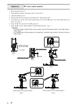
Rotary hook unit position ........................ 4 - 7
Needle clearance left/right ...................... 4 - 8
Needle bar rising..................................... 4 - 9
Needle bar height.................................. 4 - 10
Clearance between needle and rotary hook point ... 4 - 11
Needle threader .................................... 4 - 12
Presser bar height and parallelism ....... 4 - 13
Forward/backward feed ........................ 4 - 14
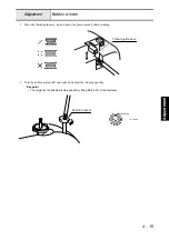
Bobbin winder ....................................... 4 - 15
BH lever switch position........................ 4 - 16
Needle and presser foot front/back position ..... 4 - 17
Front/back and left/right position of feed dog.... 4 - 18
Feed dog height .................................... 4 - 19
Inner rotary hook bracket position......... 4 - 20
Inner rotary hook assy. (lower thread) tension ... 4 - 21
Pattern .................................................. 4 - 22
Summary of Contents for HS-3000
Page 1: ......
Page 2: ......
Page 3: ......
Page 9: ...vi ...
Page 16: ...2 1 2 Disassembly Main parts 2 2 Feed unit 2 22 Needle presser unit 2 30 ...
Page 17: ...2 2 Main parts Main parts location diagram Main unit ...
Page 37: ...2 22 Feed unit location diagram Main unit ...
Page 45: ...2 30 Needle presser unit location diagram Main unit ...
Page 55: ...3 2 Main parts Main parts location diagram Main unit ...
Page 77: ...3 24 Main unit Main parts 36 Accessory table attachment 1 Attach the accessory table 1 1 ...
Page 78: ...3 25 Assembly Feed unit Feed unit location diagram Main unit ...
Page 90: ...3 37 Assembly Needle presser unit Needle presser unit location diagram Main unit ...
Page 163: ...7 12 ...
Page 164: ......


