5 - 12
Failure Investigation
for Electronic Parts
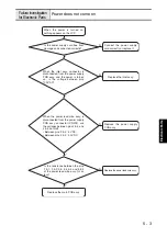
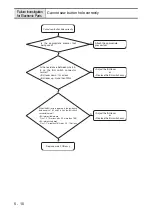
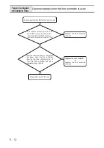
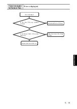
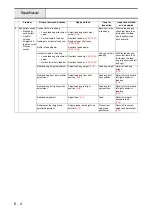
Does not operate when the foot controller is used
Does not operate when the foot controller is used.
Replace the foot controller
jack assy.
N
Is the resistance between pins 2 & 3 on the
foot controller jack assy. connector normal?
• Foot controller disconnected : 1
Ω
or less
• Foot controller connected : more than 1M
Ω
Y
Replace the foot controller.
or
Replace the foot controller
jack assy.
N
Y
When the foot controller is connected
and press down the foot controller,
does the resistance between pins 1 &
3 on the foot controller jack assy.
connector vary 1-51K
Ω
?
Replace the main PCB assy.
Summary of Contents for HS-3000
Page 1: ......
Page 2: ......
Page 3: ......
Page 9: ...vi ...
Page 16: ...2 1 2 Disassembly Main parts 2 2 Feed unit 2 22 Needle presser unit 2 30 ...
Page 17: ...2 2 Main parts Main parts location diagram Main unit ...
Page 37: ...2 22 Feed unit location diagram Main unit ...
Page 45: ...2 30 Needle presser unit location diagram Main unit ...
Page 55: ...3 2 Main parts Main parts location diagram Main unit ...
Page 77: ...3 24 Main unit Main parts 36 Accessory table attachment 1 Attach the accessory table 1 1 ...
Page 78: ...3 25 Assembly Feed unit Feed unit location diagram Main unit ...
Page 90: ...3 37 Assembly Needle presser unit Needle presser unit location diagram Main unit ...
Page 163: ...7 12 ...
Page 164: ......

