3 - 43
Needle-presser unit
Main unit
Assembly
9
Presser bar attachment
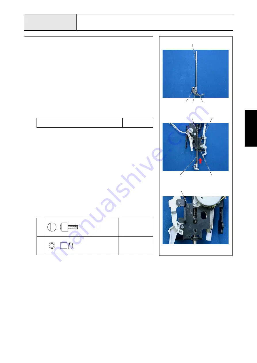
1. Attach the presser feed holder assy.
2
to the presser bar
1
with the screw
1
.
2. Attach the J foot
3
.
3. Apply a light covering of OILER to the circumference of the presser bar
1
(upper 20 mm).
4. Insert the lower end of the presser bar
1
into the base holder
4
, and then
attach the presser bar
1
, presser bar clamp
5
, and spring
6
in this order
to the base holder
4
.
5. Temporarily tighten the screw
2
to the presser bar clamp
5
.
*Key point
• Tighten after performing "4 - 13 Presser bar height and
• Adjust the distance from the base holder bottom face to the tip
of the presser bar
1
to approximately 50 mm.
Apply OILER to the circumference of the presser bar
(upper 20 mm).
Light covering
XZ0206***
1
Torque
1.18 — 1.57 N
·
m
2
Torque
Hand tighten
1
4
6
5
2
1
1
2
3
Screw
3.57
Screw stud
M5
Summary of Contents for HS-3000
Page 1: ......
Page 2: ......
Page 3: ......
Page 9: ...vi ...
Page 16: ...2 1 2 Disassembly Main parts 2 2 Feed unit 2 22 Needle presser unit 2 30 ...
Page 17: ...2 2 Main parts Main parts location diagram Main unit ...
Page 37: ...2 22 Feed unit location diagram Main unit ...
Page 45: ...2 30 Needle presser unit location diagram Main unit ...
Page 55: ...3 2 Main parts Main parts location diagram Main unit ...
Page 77: ...3 24 Main unit Main parts 36 Accessory table attachment 1 Attach the accessory table 1 1 ...
Page 78: ...3 25 Assembly Feed unit Feed unit location diagram Main unit ...
Page 90: ...3 37 Assembly Needle presser unit Needle presser unit location diagram Main unit ...
Page 163: ...7 12 ...
Page 164: ......


