4 - 12
Adjustment
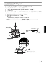
Needle threader
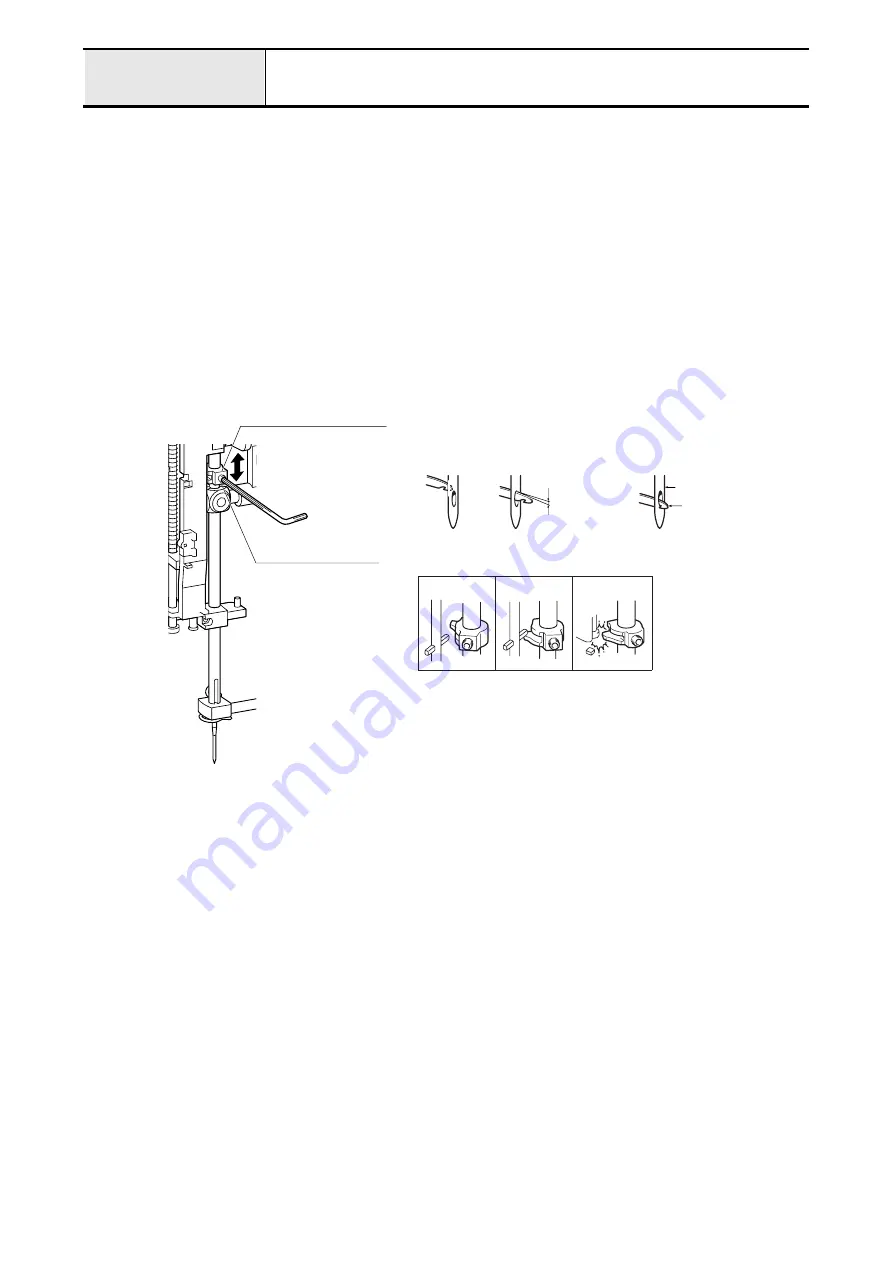
1. Attach the size 75/11 needle.
2. Turn the pulley by hand and move the needle to its highest point.
3. Loosen the socket set screw (FT, M4 x 4) of the needle thread block.
4. Loosen the socket screw (FT, M4 x 4), then move needle thread block up and down and adjust the clearance
between the upper edge of hook and the upper edge of needle eye is 0mm. After that, tighten the socket set screw
(FT, M4 x 4).
*Key point
• Tighten the socket set screw (FT, M4 x 4) at the position slightly to the left when viewed from the front of the
machine. (Fig. 2)
NOTE
• In case the position of the socket set screw (FT, M4 x 4) is too left, the hook doesn't turn. (Fig. 1)
• In case the position of the socket set screw (FT, M4 x 4) is too right, the needle thread block contacts the
needle bar supporter assy., and get damaged. (Fig. 3)
Socket set screw
(FT, M4 x 4)
Needle thread block
Needle
Upper edge of
needle eye
Upper edge
of hook
0mm
NG
NG
OK
NG
NG
OK
Fig. 1
Fig. 3
Fig. 2
Hook
Summary of Contents for HS-3000
Page 1: ......
Page 2: ......
Page 3: ......
Page 9: ...vi ...
Page 16: ...2 1 2 Disassembly Main parts 2 2 Feed unit 2 22 Needle presser unit 2 30 ...
Page 17: ...2 2 Main parts Main parts location diagram Main unit ...
Page 37: ...2 22 Feed unit location diagram Main unit ...
Page 45: ...2 30 Needle presser unit location diagram Main unit ...
Page 55: ...3 2 Main parts Main parts location diagram Main unit ...
Page 77: ...3 24 Main unit Main parts 36 Accessory table attachment 1 Attach the accessory table 1 1 ...
Page 78: ...3 25 Assembly Feed unit Feed unit location diagram Main unit ...
Page 90: ...3 37 Assembly Needle presser unit Needle presser unit location diagram Main unit ...
Page 163: ...7 12 ...
Page 164: ......


