4 - 18
Adjustment
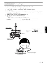
Front/back and left/right position of feed dog
1. Remove the needle plate B, the presser foot, the presser foot holder and the needle.
2. Start the test mode.
3. Select the pattern number “07” (Feed dog position mode).
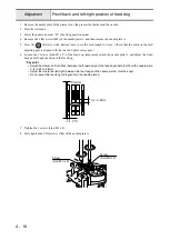
4. Remove the 2 flat screws (M4) of the needle plate A, and then remove the needle plate A.
5. Press the
(Reverse stitch button) twice to set the feed length to 0 mm. (Check that the mark on the feed
adjusting gear is aligned with that on the F pulse motor gear.)
6. Loosen the 2 screws (bind M3 x 8) of the feed dog, temporarily attach the needle plate A, and adjust the front/
back and left/right position of the feed dog.
*Key point
• Adjust the clearance (front/back) between the forward edge of the feed dog middle tooth and the needle plate
A is to 3.2 to 3.8mm.
• Adjust the clearance (left/right) between the feed dog and the needle plate A must be equal.
• Do not assemble feed dog to diagonally to the needle plate A.
7. Tighten the 2 screws (bind M3 x 8).
8. Fully tighten the 2 flat screws (M4) of the needle plate A.
Parallel
3.2 - 3.8mm
Screw
(bind M3 x 8)
Screw
(bind M3 x 8)
Summary of Contents for HS-3000
Page 1: ......
Page 2: ......
Page 3: ......
Page 9: ...vi ...
Page 16: ...2 1 2 Disassembly Main parts 2 2 Feed unit 2 22 Needle presser unit 2 30 ...
Page 17: ...2 2 Main parts Main parts location diagram Main unit ...
Page 37: ...2 22 Feed unit location diagram Main unit ...
Page 45: ...2 30 Needle presser unit location diagram Main unit ...
Page 55: ...3 2 Main parts Main parts location diagram Main unit ...
Page 77: ...3 24 Main unit Main parts 36 Accessory table attachment 1 Attach the accessory table 1 1 ...
Page 78: ...3 25 Assembly Feed unit Feed unit location diagram Main unit ...
Page 90: ...3 37 Assembly Needle presser unit Needle presser unit location diagram Main unit ...
Page 163: ...7 12 ...
Page 164: ......


