5 - 20
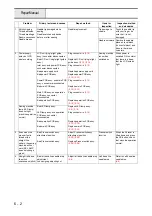
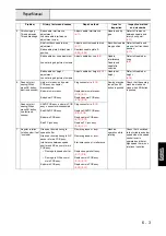
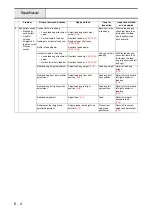
Failure Investigation
for Electronic Parts
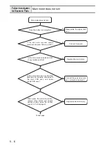
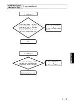
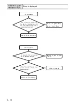
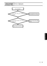
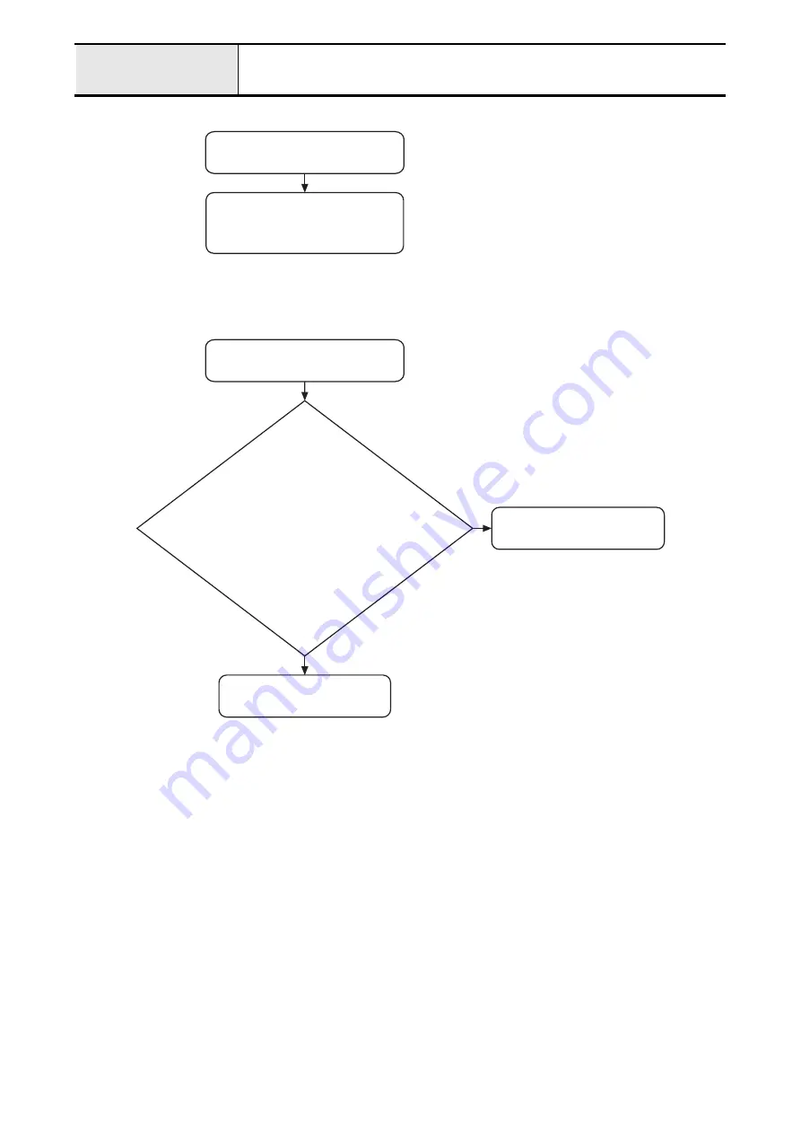
Error is displayed
Replace the SSVR PCB assy.
or
Replace the main PCB assy.
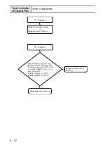
"F7" is displayed.
Replace the power supply
PCB assy.
When the power lead wire assy. is
disconnected from the power supply
PCB assy. connector (CN201), are
the voltages between pins 2 & 3
and 4 & 3 normal?
• Between pins 2 & 3 : 5V DC
• Between pins 4 & 3 : 30V DC
N
Y
Replace the main PCB assy.
"F8" is displayed.
Summary of Contents for HS-3000
Page 1: ......
Page 2: ......
Page 3: ......
Page 9: ...vi ...
Page 16: ...2 1 2 Disassembly Main parts 2 2 Feed unit 2 22 Needle presser unit 2 30 ...
Page 17: ...2 2 Main parts Main parts location diagram Main unit ...
Page 37: ...2 22 Feed unit location diagram Main unit ...
Page 45: ...2 30 Needle presser unit location diagram Main unit ...
Page 55: ...3 2 Main parts Main parts location diagram Main unit ...
Page 77: ...3 24 Main unit Main parts 36 Accessory table attachment 1 Attach the accessory table 1 1 ...
Page 78: ...3 25 Assembly Feed unit Feed unit location diagram Main unit ...
Page 90: ...3 37 Assembly Needle presser unit Needle presser unit location diagram Main unit ...
Page 163: ...7 12 ...
Page 164: ......

