2 - 7
Main parts
Main unit
Disassembly
6
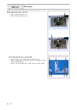
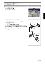
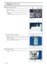
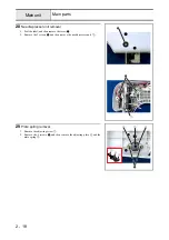
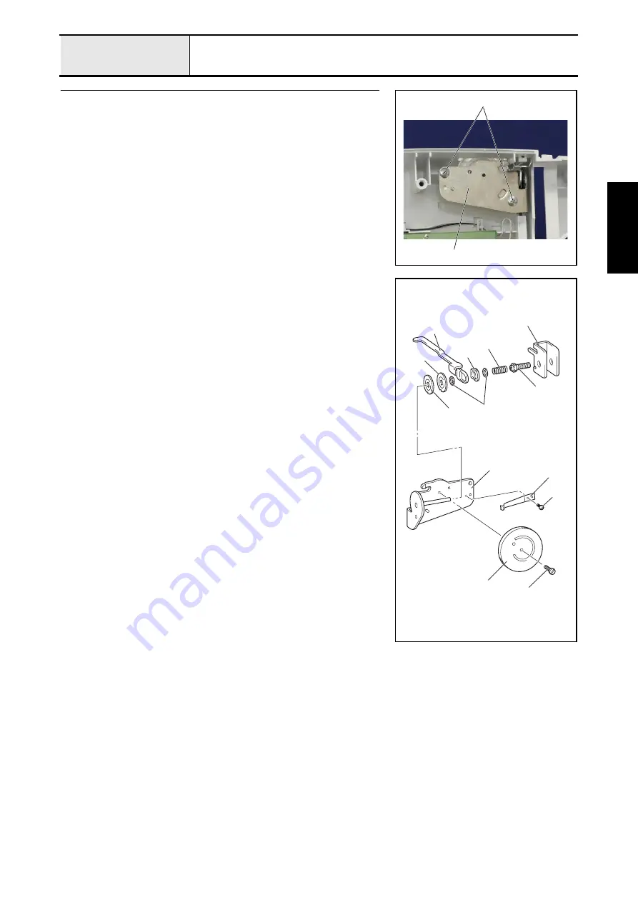
Thread guide assy. A removal
1. Remove the two screws
1
.
2. Remove the thread guide A assy.
1
.
1
1
6-1
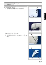
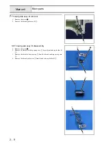
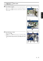
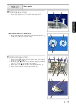
Thread guide assy. A disassembly
1. Remove the screw
1
, and then remove the notch spring
2
from the thread
tension holder assy.
1
.
2. Remove the thread dial shaft
3
.
*Key point
• Turn the dial clockwise until it stops.
3. Remove the thread tension dial
4
and the thread tension plate assy.
5
.
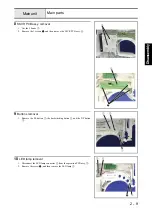
4. Remove the spring
6
, washer
7
, tension disc washer
8
, thread release
plate
9
, washer
7
, tension disc B
;
, and then tension disc A
A
in this
order from the caulking shaft of the thread tension holder assy.
1
.
5. Remove the thread tension adjusting screw
B
from the thread tension plate
assy.
5
.
1
1
5
6
8
9
0
B
A
7
3
2
4
Summary of Contents for HS-3000
Page 1: ......
Page 2: ......
Page 3: ......
Page 9: ...vi ...
Page 16: ...2 1 2 Disassembly Main parts 2 2 Feed unit 2 22 Needle presser unit 2 30 ...
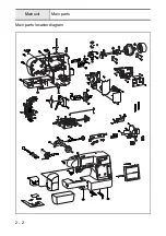
Page 17: ...2 2 Main parts Main parts location diagram Main unit ...
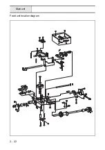
Page 37: ...2 22 Feed unit location diagram Main unit ...
Page 45: ...2 30 Needle presser unit location diagram Main unit ...
Page 55: ...3 2 Main parts Main parts location diagram Main unit ...
Page 77: ...3 24 Main unit Main parts 36 Accessory table attachment 1 Attach the accessory table 1 1 ...
Page 78: ...3 25 Assembly Feed unit Feed unit location diagram Main unit ...
Page 90: ...3 37 Assembly Needle presser unit Needle presser unit location diagram Main unit ...
Page 163: ...7 12 ...
Page 164: ......


