3 - 46
Needle-presser unit
Main unit
11
Needle bar assy. attachment
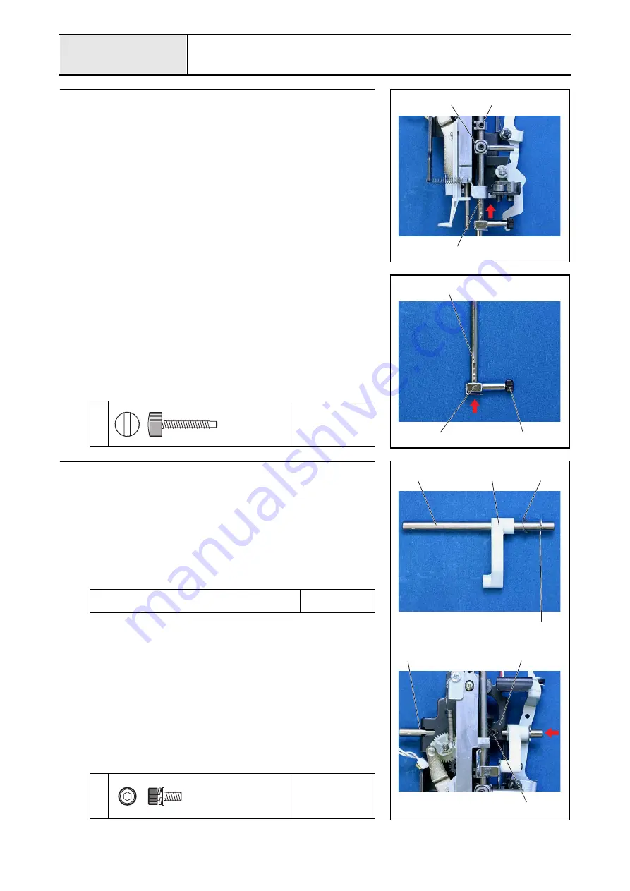
1. Insert the needle bar assy.
1
from the bottom of the needle holder assy.,
and then insert the needle bar block
2
and the needle thread block
3
through the needle bar assy. and then through to the upper hole.
*Key point
• Insert the needle bar block
2
and the needle thread block
3
so that the shaft of the needle bar block
2
is on the right side
and the tab of the needle thread block
3
is on the left side.
2
3
1
11-1
Needle bar assy. assembly
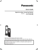
1. Attach the presser feed holder assy.
1
to the needle bar assy.
2
with the
screw
1
.
*Key point
• The screw
1
should be on the right side when the groove on
the needle bar assy.
2
faces the front.
1
1
2
1
Needle Clamp Screw
12
Thread take-up lever link attachment
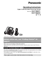
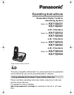
1. Insert the shaft
1
into the base holder
2
, and then align the screw
1
with
the trench on the base holder
2
, and tighten it temporarily.
2. Attach the thread take-up lever link
3
.
3. Apply a light covering of MOLYKOTE EM-30L to the circumference of
the shaft within 10 mm of the retaining ring.
4. Insert the spring washer
4
into the shaft
1
.
5. Attach the retaining ring (E5) to the groove on the shaft
1
.
Apply MOLYKOTE EM-30L to the circumference of the
shaft within 10 mm of the retaining ring.
Light covering
XC8385***
1
Torque
Hand tighten
1
3
4
Retaining ring E5
1
1
2
Screw
M3X8
Summary of Contents for HS-3000
Page 1: ......
Page 2: ......
Page 3: ......
Page 9: ...vi ...
Page 16: ...2 1 2 Disassembly Main parts 2 2 Feed unit 2 22 Needle presser unit 2 30 ...
Page 17: ...2 2 Main parts Main parts location diagram Main unit ...
Page 37: ...2 22 Feed unit location diagram Main unit ...
Page 45: ...2 30 Needle presser unit location diagram Main unit ...
Page 55: ...3 2 Main parts Main parts location diagram Main unit ...
Page 77: ...3 24 Main unit Main parts 36 Accessory table attachment 1 Attach the accessory table 1 1 ...
Page 78: ...3 25 Assembly Feed unit Feed unit location diagram Main unit ...
Page 90: ...3 37 Assembly Needle presser unit Needle presser unit location diagram Main unit ...
Page 163: ...7 12 ...
Page 164: ......


