background image

3-8

Confidential

2

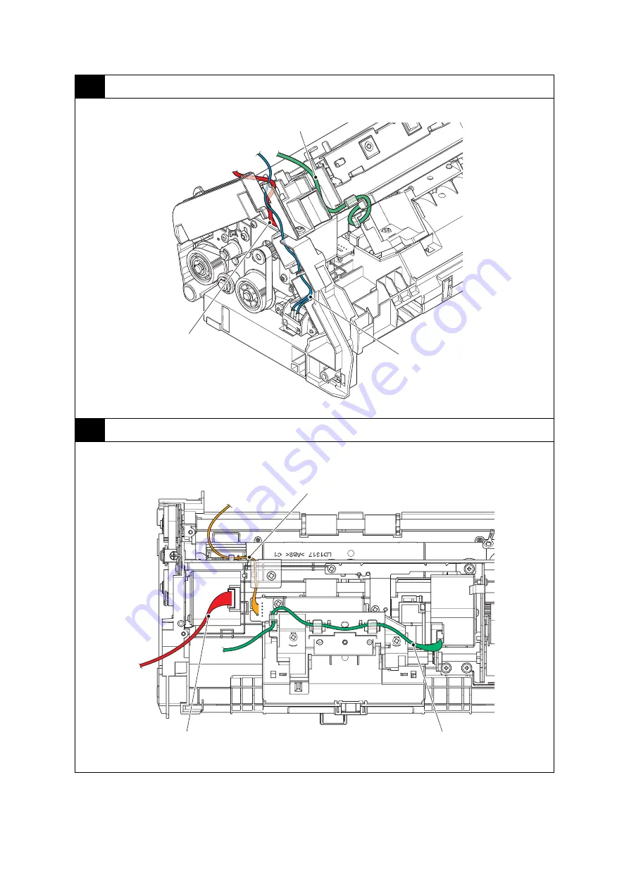
Right side of the machine

3

Rear side of the machine

Harness colors are subject to change for some reason.

Front cover sensor harness 
(WH)

Feed motor harness (RD)

Paper feed motor harness (BK)

Paper feed motor harness (BK)

Feed motor harness (RD)

Multi feeding sensor harness (Receive) 
(RD, BK, WH, BL)

Summary of Contents for ImageCenter ADS-2400N

Page 1: ...her Advanced Document Scanner SERVICE MANUAL MODEL ADS 2400N 3000N Read this manual thoroughly before maintenance work Keep this manual in a convenient place for quick and easy reference at all times Nov 2015 SM PT083 1 ...

Page 2: ...tion may be reproduced in any form or by any means without permission in writing from the publisher All other product and company names mentioned in this manual are trademarks or registered trademarks of their respective holders Specifications are subject to change without notice ...

Page 3: ... Adobe and Photoshop are either registered trademarks or trademarks of Adobe Systems Incorporated in the United States and or other countries Each company whose software title is mentioned in this manual has a Software License Agreement specific to its proprietary programs Any trade names and product names of companies appearing on Brother products related documents and any other materials are all...

Page 4: ... 3 Operation of Each Part 2 5 2 4 Block Diagram 2 6 2 5 Main Components 2 7 3 ERROR INDICATIONS 2 8 3 1 LED Display when an Error Occurs 2 8 3 2 Status Error Messages 2 11 4 TROUBLESHOOTING 2 12 4 1 Troubleshooting for Error Display 2 12 4 1 1 All scanned data are printed as blank page 2 12 4 1 2 The scanned data has exceeded the memory capacity when using USB The number of files or folders has ex...

Page 5: ...ng 2 15 4 1 15 An USB device not within the specification is connected to the USB terminal resulting in overcurrent A non supported USB device is connected to the USB terminal An USB device with a built in hub is connected to the USB terminal USB flash memory is blocked from writing USB flash memory is disconnected or inaccessible 2 15 4 1 16 Color parameter in the ROM does not match the first sid...

Page 6: ...er L R 3 27 9 8 Front cover ASSY 3 29 9 9 Panel unit Panel flat cable Key PCB ASSY Rubber key 3 30 9 10 Second side CIS unit Second side CIS flat cable Flat cable support film 3 32 9 11 Eject jam sensor PCB 3 34 9 12 Document scanning position sensor PCB 3 35 9 13 Paper feed jam sensor PCB Multi feeding sensor PCB ASSY Sent 3 38 9 14 Document detection sensor PCB ASSY 3 40 9 15 First side CIS unit...

Page 7: ...OU REPLACE THE PICK UP ROLLER REVERSE ROLLER 4 19 4 1 Resetting Pick Up Roller Reverse Roller Counters 4 19 CHAPTER 5 SERVICE FUNCTIONS 1 MAINTENANCE MODE 5 1 1 1 How to Enter Maintenance Mode 5 1 1 1 1 Method of entering maintenance mode for service personnel 5 1 1 1 2 Method of entering end user accessible maintenance mode 5 1 1 2 List of Maintenance Mode Functions 5 2 1 3 Details of Maintenance...

Page 8: ...ity Prohibition icons indicate actions that must not be performed Electrical Hazard icons alert you to possible electrical shock Fire Hazard icons alert you to the possibility of fire Unplug icons indicate that you should unplug the machine Note Notes indicates advice about how you should respond to a situation that may arise with your machine and or advice about how the operation of the machine w...

Page 9: ...ular organic solvents or liquids such as benzene paint thinner polish remover or deodorizer may melt or dissolve the plastic cover and or cables resulting in a risk of fire or electric shock These or other chemicals may also cause the machine to malfunction or become discolored The product should be placed so as not to come into contact with any wall or other device Otherwise it could create a ris...

Page 10: ...el and stable surface free from vibration Failure to observe these precautions could cause the machine to fall causing injury to you or others and serious damage to the machine Important DO NOT place your machine next to sources of interference such as speakers or the base units of non Brother cordless telephones Doing so may interfere with the operation of the machine s electronic components DO N...

Page 11: ...rom the AC power outlet and contact Brother Authorized Service Personnel Power Cord Safety Use only the power cord supplied with this product DO NOT allow anything to rest on the power cord DO NOT place the machine where people can walk on the cord DO NOT place the machine in a position where the cord is stretched or strain is otherwise put on the cord as it may become worn or frayed DO NOT use th...

Page 12: ...is used during a thunderstorm When disconnecting the AC adapter from the machine or from the power outlet always hold the connector not the cable and pull firmly Failure to do so may result in exposed or broken power cord wires and or create a risk of fire or electric shock Make sure that one end of the power cord is firmly plugged into a standard power outlet and the other end is firmly plugged i...

Page 13: ...he machine becomes hot releases smoke or generates any strong or unusual odors immediately unplug the machine from the power outlet and call Brother Customer Service DO NOT touch the AC adapter or handle the plug with wet hands CAUTION DO NOT put pressure or weight on the unit or use it for any purpose beyond its intended purpose Wait until pages have exited the machine before taking them out or y...

Page 14: ...kaged in a plastic bag To avoid suffocation keep this plastic bag away from babies and children Do not use the bag in cribs beds carriages or play pens The bag is not a toy Important Disruption of power can wipe out information in the machine s memory DO NOT put objects on top of the unit If the machine does not operate normally when the operating instructions are followed adjust only those contro...

Page 15: ...4 LTR Two sided Color 60 ipm 30 ppm 300 dpi 2 0 seconds A4 LTR 100 ipm 50 ppm 300 dpi 1 2 seconds A4 LTR CPU Cortex A9 800 MHz Memory 256 MB Interface USB Hi Speed 2 0 10 Base T 100 Base TX 1000 Base T USB Super Speed 3 0 10 Base T 100 Base TX 1000 Base T Power consumption Scanning Approximately 27 W Approximately 30 W Ready Approximately 3 W Approximately 4 1 W Deep Sleep Approximately 1 9 W Appr...

Page 16: ...or equivalent 150 MB 1 GB Windows Vista 2 Intel Pentium 4 or equivalent 64 bit Intel 64 or AMD 64 supported CPU 500 MB Windows 7 2 650 MB Windows 8 Windows 8 1 Windows Server 2003 only 32 bit Windows Server 2008 Windows Server 2008 R2 Windows Server 2012 Windows Server 2012 R2 3 Macintosh Operating System OS X v10 8 5 Intel Processor 80 MB 1 GB OS X v10 9 x OS X v10 10 x 1 Third party USB ports ar...

Page 17: ... T Network security SMTP AUTH SSL TLS HTTPS SMTP SNMP v3 802 1x EAP MD5 EAP FAST PEAP EAP TLS EAP TTLS Kerberos IPsec Wireless network Network node type N A Network type N A Communication mode N A Network security N A Part Approximate Life pages Machine life 500 000 sheets A4 LTR MTBF 4 000 hours MTTR 0 5 hours Maximum monthly volume ADS 2400N 60 000 sheets A4 LTR ADS 3000N 100 000 sheets A4 LTR P...

Page 18: ...e Part All Models ADF Input 50 sheets ADF Output 50 sheets Duplex Scan Yes Part All Models Paper Input ADF Plain Paper Thin Paper Thick Paper Thicker Paper Recycled Paper Post Card JPN Business Card Plastic Card Media Weight ADF multiple paper 27 to 413 g m2 ADF single paper Plain paper Long paper 40 to 209 g m2 Thick paper 209 to 413 g m2 Media Size ADF multiple paper Width 51 to 215 9 mm Length ...

Page 19: ...1 Windows Vista Windows 7 8 8 1 10 ICA Compliant Macintosh OS X 10 8 x 10 9 x 10 10 x Download only 2 ISISTM Compliant Windows Windows Vista Windows 7 8 8 1 10 Color Depth Input 30 bit color Processing Output 24 bit color Processing Resolution Interpolated Up to 1200 x 1200 dpi Optical Up to 600 x 600 dpi Scanning Width Up to 215 mm Gray Scale 256 levels 1 Windows XP in this Service Manual include...

Page 20: ...ng troubleshooting 1 Be sure to unplug the AC power cord before removing any covers or PCBs adjusting the machine or conducting continuity tests using a tester 2 Do not hold the cable when connecting or disconnecting the cable Be sure to hold the connector 3 Static electricity charged in your body may damage electronic parts Before handling the PCBs touch a metal section of the machine to discharg...

Page 21: ...ded paper is used for the document Refer to 5 2 Media Specifications in Chapter 1 2 The document is not damp 3 Acid paper is not used Others 1 Condensation When the machine is moved to a warm room from a cold location condensation may occur inside the machine causing various problems as listed below Condensation on the surface of optical devices such as the CIS glass and CIS unit may result in poo...

Page 22: ...ect jam actuator Duplex scanning speed 100 ipm model only Output tray Eject roller Document tray Multi feeding sensor Receive Pick up roller Paper feed jam actuator Duplex scanning speed 100 ipm model only Feed roller First side CIS unit Multi feeding sensor Sent Reverse roller Document stopper Document detection actuator ...

Page 23: ...2 4 Confidential 2 2 Paper Feeding Fig 2 2 Feed path Front side Back side ...

Page 24: ...r Document detection sensor Detects the document in the document tray Detects document jams Document scanning position actuator Document scanning position sensor Detects document jams Determines whether the document is fed from the document tray Detects document pass and adjusts the scanning start position for the document Paper feed jam actuator Paper feed jam sensor Detects document jams in the ...

Page 25: ...i feeding sensor PCB ASSY Sent Multi feeding sensor PCB ASSY Receive Document detection sensor PCB Document scanning position sensor PCB Main PCB DC jack LAN USB host PCB Duplex Scanning Speed 100 ipm model only Paper feed jam sensor PCB Eject jam sensor PCB USB3 0 USB2 0 Duplex Scanning Speed 100 ipm model Duplex Scanning Speed 60 ipm model ...

Page 26: ...SY Main PCB ASSY Bottom cover ASSY Exit stopper Paper feed motor USB host PCB ASSY Feed motor Multi feeding sensor PCB ASSY Receive Document scanning position sensor PCB Side cover L Feed belt Front cover L Front cover sensor First side CIS unit Rubber key Second side CIS unit Pick up roller Multi feeding sensor PCB ASSY Sent Eject jam sensor Front cover ASSY ...

Page 27: ...ceeded the memory capacity when using USB 4 1 2 The number of files or folders has exceeded the upper limit when using USB 4 1 2 USB flash memory is blocked from writing 4 1 15 USB flash memory is disconnected or inaccessible 4 1 15 Cleaning counter of both reverse roller and pick up roller has exceeded the specified value 4 1 14 The page counter of the pick up roller has reached the limit and its...

Page 28: ... the Long Paper setting was used 4 1 8 The multi feeding sensor detected multiple documents 4 1 9 The front cover sensor detected an open front cover 4 1 10 The page counter for the reverse roller has reached the limit 4 1 11 The page counter for the pick up roller has reached the limit 4 1 11 The page counter for the reverse roller and pick up roller have reached the limit 4 1 11 The cleaning cou...

Page 29: ...hose displays A non supported USB device is connected to the USB terminal 4 1 15 An USB device with a built in hub is connected to the USB terminal 4 1 15 LED By pressing X Type of problem Refer to Color parameter in the ROM does not match the first side or second side CIS unit 4 1 16 A scanning error occurred while scanning the image 4 1 17 LED Type of problem Refer to 1 2 3 1 2 3 1 2 3 1 2 3 1 2...

Page 30: ...ed amount 4 1 18 Replace Reverse Roller The page counter for the reverse roller has reached the limit 4 1 11 Replace pick up Roller The page counter for the pick up roller has reached the limit 4 1 11 Replace pick up and reverse roller The page counter for the reverse roller and pick up roller have reached the limit 4 1 11 Too Many Files on USB The number of files or folders has exceeded the upper...

Page 31: ...a has exceeded the memory capacity of the machine when WSScan was executed Step Cause Remedy 1 The maintenance mode function Acquire white level data and set CIS scan area are not set Execute the maintenance mode function Acquire white level data and set CIS scan area Refer to 1 3 5 in Chapter 5 2 Main PCB failure Replace the main PCB ASSY User Check Perform scanning by dividing the document Use a...

Page 32: ...hat the document guide is adjusted to suit the document size Step Cause Remedy 1 Reverse roller cover attachment failure Reattach the reverse roller cover 2 Pick up roller cover attachment failure Reattach the pick up roller cover 3 Document scanning position actuator caught in a section of the machine Reattach the document scanning position actuator 4 Attachment failure of the first side or secon...

Page 33: ...tep Cause Remedy 1 Reverse roller attachment failure Reattach the reverse roller 2 Pick up roller attachment failure Reattach the pick up roller 3 Setting failure of the multi feeding sensor Reset the multi feeding sensor threshold 4 Multi feeding sensor failure Replace the multi feeding sensor 5 Main PCB failure Replace the main PCB ASSY User Check Check that the front cover is closed correctly S...

Page 34: ... Replace the reverse roller and pick up roller and reset the counter Clean it and reset the regular cleaning counter Step Cause Remedy 1 Main PCB failure Replace the main PCB ASSY User Check Resume the interrupted scanning Step Cause Remedy 1 Rubber key attachment failure Reattach the rubber key 2 Rubber key failure Replace the rubber key 3 Panel PCB failure Replace the panel PCB ASSY 4 Main PCB f...

Page 35: ...de function Acquire white level data and set CIS scan area are not set Execute the maintenance mode function Acquire white level data and set CIS scan area Refer to 1 3 5 in Chapter 5 3 First side or second side CIS unit failure Replace the first side or second side CIS unit 4 Main PCB failure Replace the main PCB ASSY User Check Check the email address settings Step Cause Remedy 1 Main PCB failur...

Page 36: ...ion data Execute the maintenance mode function Acquire white level data and set CIS scan area Refer to 1 3 5 in Chapter 5 2 Dirty calibration sheet Replace the calibration sheet with a new one 3 First side or second side CIS unit failure Replace the first side or second side CIS unit 4 Main PCB failure Replace the main PCB ASSY Light White vertical streaks Vertical streaks Completely blank Hue def...

Page 37: ...hapter 5 2 Dirty calibration sheet Replace the calibration sheet with a new one 3 First side or second side CIS unit failure Replace the first side or second side CIS unit 4 Main PCB failure Replace the main PCB ASSY User Check Check that the document is not reversed Check that the document is set in the document tray correctly Step Cause Remedy 1 Incorrect white level correction data Execute the ...

Page 38: ...ean the feeding path Step Cause Remedy 1 First side or second side CIS unit failure Replace the first side or second side CIS unit User Check Clean the document glass or CIS glass Step Cause Remedy 1 Color parameter failure Execute the maintenance mode function Acquire white level data and set CIS scan area Refer to 1 3 5 in Chapter 5 2 Dirty calibration sheet Replace the calibration sheet with a ...

Page 39: ...he first side or second side CIS unit 4 Main PCB failure Replace the main PCB ASSY User Check Clean the feeding path Moisten a soft cloth with cleaning solution Gently and evenly wipe the pick up roller and reverse roller perpendicular to the direction of the rotation with the cloth to clean it Note Do not use any solution except the one packaged in the accessory ethanol or detergent on the market...

Page 40: ...or PCB harness Reconnect the document detection sensor PCB harness 6 Attachment failure of the gears in a feeding system Reattach the gears in a feeding system 7 Front cover sensor failure Replace the front cover sensor 8 Document detection sensor failure Replace the document detection sensor PCB 9 Feed motor failure Replace a feed motor ASSY 10 Main PCB failure Replace the main PCB ASSY User Chec...

Page 41: ...k that the front cover is closed correctly Step Cause Remedy 1 Foreign object inside the front cover Remove the foreign object inside the front cover 2 Document scanning position actuator coming off Reattach the document scanning position actuator 3 Document pinch roller coming off Reattach the document pinch roller 4 Connection failure of the document scanning position sensor PCB harness Reconnec...

Page 42: ...he latest version of the firmware Refer to 1 1 in Chapter 4 2 Connection failure of the front cover sensor harness Reconnect the front cover sensor harness 3 Rubber key attachment failure Reattach the rubber key 4 Front cover sensor failure Replace the front cover sensor ASSY 5 Main PCB failure Replace the main PCB ASSY User Check Check that the USB cable or LAN cable is not damaged When using an ...

Page 43: ... Panel PCB failure Replace the panel PCB ASSY 5 Main PCB failure Replace the main PCB ASSY Step Cause Remedy 1 Rubber key attachment failure Reattach the rubber key 2 Connection failure of the panel PCB harness Reconnect the panel PCB harness 3 Panel PCB attachment failure Reattach the panel PCB ASSY 4 Rubber key failure Replace the rubber key 5 Panel PCB failure Replace the panel PCB ASSY 6 Main ...

Page 44: ...e sure that there is no other function running Step Cause Remedy 1 Firmware version does not match Install the latest version of the firmware Refer to 1 1 in Chapter 4 2 Main PCB failure Replace the main PCB ASSY User Check Check that the USB flash memory is inserted into the USB terminal correctly Replace the USB flash memory and try saving data again Check that the USB flash memory is not write ...

Page 45: ...eets When replacing the PCB and all the other related parts put on a grounding wrist band and perform the job on a static mat Also take care not to touch the conductor sections on the flat cables or on the wire harnesses After disconnecting flat cables check that each cable is not damaged at its end or short circuited When connecting flat cables do not insert them at an angle After insertion check...

Page 46: ...3 2 Confidential 2 PACKING ...

Page 47: ...3 3 Confidential 3 SCREW CATALOGUE Taptite bind B Taptite cup B Taptite bind B M4x10 Taptite bind B M3x8 Taptite cup B M3x10 Screw bind Screw cup Screw cup M3x6 Screw bind M3x6 Taptite cup B M2 6x10 BK ...

Page 48: ... 7 0 1 7 1 FG spring B Screw cup M3x6 1 0 7 0 1 7 1 EJ pinch roller support plate Taptite bind B M3x8 2 0 5 0 1 5 1 Sensor holder C Taptite bind B M3x8 1 0 5 0 1 5 1 Reverse roller holder support Screw cup M3x6 2 0 7 0 1 7 1 Pinch roller support Taptite bind B M3x8 1 0 5 0 1 5 1 FG spring Screw cup M3x6 1 0 7 0 1 7 1 Document scanning position actuator holder Taptite bind B M3x8 2 0 5 0 1 5 1 PF p...

Page 49: ...3 5 Confidential 5 LUBRICATION There are no applicable parts for lubrication ...

Page 50: ...3 6 Confidential 6 OVERVIEW OF GEARS There are no gears to be disassembled ...

Page 51: ...at cable Front cover sensor harness WH Multi feeding sensor harness Sent WH BK Paper feed Eject jam sensor harness BL RD FG harness GR Feed motor harness RD Paper feed motor harness BK Panel flat cable First side CIS flat cable Document detection Document scanning position sensor harness GR WH Multi feeding sensor harness Receive RD BK WH BL ...

Page 52: ... side of the machine Harness colors are subject to change for some reason Front cover sensor harness WH Feed motor harness RD Paper feed motor harness BK Paper feed motor harness BK Feed motor harness RD Multi feeding sensor harness Receive RD BK WH BL ...

Page 53: ...hange for some reason FG harness GR Panel flat cable Second side CIS flat cable Multi feeding sensor harness Sent WH BK Document detection sensor harness GR Document scanning position sensor harness WH Paper feed jam sensor harness RD Eject jam sensor harness BL ...

Page 54: ...r L 5 5 9 13 Paper feed jam sensor PCB Multi feeding sensor PCB ASSY Sent 60 90 9 10 Second side CIS flat cable 15 40 9 9 Key PCB ASSY Rubber key 5 5 9 9 Back up plate base 25 50 9 9 Panel unit 40 50 9 10 Second side CIS unit 5 5 9 16 Front cover ASSY 20 20 9 16 Front cover sensor 10 15 9 9 Panel flat cable 5 20 9 12 Document scanning position sensor PCB 65 125 9 13 Paper feed jam sensor PCB Multi...

Page 55: ... to proceeding with the disassembly procedure 1 Disconnect the following AC adapter AC power cord USB cable if connected LAN cable if connected USB flash memory if connected 2 Remove the following Document tray LAN port cap Fig 3 1 USB cable AC adapter LAN cable LAN port cap USB flash memory Document tray ...

Page 56: ...oller 1 Push the release button and open the front cover ASSY 2 Open the reverse roller cover to remove the reverse roller from the machine Fig 3 2 3 Close the reverse roller cover Reverse roller Release button Front cover ASSY Reverse roller cover ...

Page 57: ... Fig 3 3 6 Close the pick up roller cover and then the front cover ASSY Assembling Note When attaching the pick up roller make sure that the lever hook is engaged with the groove on the machine If not the pick up roller wears out quickly because it comes in contact with the pick up roller cover Pick up roller Pick up roller cover Lever A Groove Lever hook ...

Page 58: ... and remove the bottom cover ASSY from the machine Fig 3 4 2 Remove the two stoppers and remove the exit tray ASSY from the bottom cover ASSY 3 Remove the exit stopper from the exit tray ASSY Fig 3 5 Bottom cover ASSY Taptite bind B M3x8 Stopper Bottom cover ASSY Stopper Exit tray ASSY Exit stopper ...

Page 59: ...r 1 Push the release button and open the front cover ASSY 2 Open the pick up roller cover to remove the two taptite cup B M3x10 screws from the machine Fig 3 6 Pick up roller cover Taptite cup B M3x10 Front cover ASSY Release button ...

Page 60: ...3 16 Confidential 3 Release the four hooks to remove the back cover from the machine in the direction of the arrow Fig 3 7 4 Close the pick up roller cover Hooks Hooks Back cover ...

Page 61: ...3 17 Confidential 9 4 Side cover L R 1 Release the three hooks and remove the side cover L from the machine Fig 3 8 Hooks Hook Side cover L ...

Page 62: ...3 18 Confidential 2 Release the three hooks and remove the side cover R from the machine Fig 3 9 3 Close the front cover ASSY Hook Side cover R Hooks ...

Page 63: ... 2 Remove the three taptite cup B M3x10 screws and remove the USB host FG plate from the machine 3 Remove the USB host PCB ASSY from the machine Fig 3 10 HARNESS ROUTING Refer to 1 Main PCB ASSY Taptite cup B M3x10 USB host FG plate Taptite cup B M3x10 USB host PCB ASSY USB host PCB harness Second side CIS flat cable Main PCB ASSY ...

Page 64: ...onnected to the main PCB ASSY Fig 3 12 HARNESS ROUTING Refer to 1 Main PCB ASSY Main PCB upper shield Copper seal Main PCB ASSY First side CIS flat cable Panel flat cable Feed motor harness Paper feed motor harness Multi feeding sensor harness Sent Multi feeding sensor harness Receive Frontcoversensor harness Document detection Document scanning position sensor harness Paper feed Eject jam sensor ...

Page 65: ...m the machine Fig 3 13 4 Remove the three taptite cup B M3x10 screws to remove the FG harness GR and main PCB upper lower shield from the machine Fig 3 14 HARNESS ROUTING Refer to 1 Main PCB ASSY Taptite bind B M3x8 Drive earth plate Taptite cup B M3x10 Main PCB upper lower shield FG harness GR ...

Page 66: ...15 Fig 3 16 Assembling Note When assembling the main PCB upper shield insert the two ribs of the main PCB upper shield below the main PCB lower shield When opening the main PCB upper shield take care not to break the copper seal If the copper seal is broken replace it with a new one Ribs Screw cup M3x6 Main PCB lower shield Main PCB upper shield Copper seal Ribs Main PCB lower shield Copper seal 3...

Page 67: ...emove the heat conductive sheet B and heat conductive sheet A from the main PCB ASSY Fig 3 18 Assembling Note Attach the heat conductive sheet A and heat conductive sheet B in the red frame described in the figure above Screw cup M3x6 Main PCB ASSY Main PCB lower shield Heat conductive sheet B Heat conductive sheet A Main PCB ASSY ...

Page 68: ...ribs of the main PCB upper shield below the main PCB lower shield When assembling the main PCB upper shield make sure to check that the main PCB upper shield is in contact with the radio wave absorptive sheet properly as shown in the figure above Main PCB upper shield Main PCB upper shield Main PCB upper shield Screw cup M3x6 Ribs Ribs Main PCB lower shield Main PCB lower shield Radio wave absorpt...

Page 69: ...ws and remove the main PCB ASSY from the machine Fig 3 21 Main PCB ASSY First side CIS flat cable Panel flat cable Feed motor harness Paper feed motor harness Multi feeding sensor harness Sent Multi feeding sensor harness Receive Front cover sensor harness Document detection Document scanning position sensor harness Paper feed Eject jam sensor harness Screw cup M3x6 Main PCB ASSY ...

Page 70: ...et B and heat conductive sheet A from the main PCB ASSY Fig 3 22 Assembling Note Attach the heat conductive sheet A and heat conductive sheet B in the red frame described in the figure above Heat conductive sheet B Heat conductive sheet A Main PCB ASSY ...

Page 71: ... 1 Release the hook of the front cover L and remove the front cover L from the machine Fig 3 23 Assembling Note When assembling the front cover L engage the slit of the front cover L with the rib of the machine Slit Front cover L Rib Hook ...

Page 72: ... the hook of the front cover R and remove the front cover R from the machine Fig 3 24 Assembling Note When assembling the front cover R engage the slit of the front cover R with the rib of the machine Slit Front cover R Rib Hook ...

Page 73: ...Release all the panel unit harnesses from the securing fixtures 2 Push the release button and open the front cover ASSY 3 Remove the two bosses and remove the front cover ASSY from the machine Fig 3 25 Boss Front cover ASSY Boss Release button ...

Page 74: ...B M2 6x10 BK screws 2 Release the four tabs to lift the front cover ASSY Slide the panel unit in the direction of the arrow to release the four hooks and remove the panel unit from the front cover ASSY Fig 3 26 Taptite cup B M2 6x10 BK Tabs Front cover ASSY Hooks Hooks Panel unit Taptite cup B M2 6x10 BK ...

Page 75: ...er key and address label from the panel unit Fig 3 27 HARNESS ROUTING Refer to 4 Panel unit Fig 3 28 Assembling Note When connecting the panel flat cable fold it as shown in the figure below Taptite cup B M2 6x10 BK Back up plate base Panel flat cable Key PCB ASSY Rubber key Panel unit Address label 89 8 2 45 45 Reinforcing plate Mountain fold at the end of reinforcing plate 13 90 70 32 Key PCB si...

Page 76: ...two ribs outwards to remove the second side CIS unit from the front cover ASSY Disconnect the second side CIS flat cable from the second side CIS unit 2 Remove the second side CIS spring from the machine Fig 3 29 Second side CIS unit Rib Second side CIS flat cable Rib Second side CIS spring Front cover ASSY ...

Page 77: ...ve force once it is removed Replace it with a new one Assembling Note When securing the flat cable support film with the double sided tapes attach the tape on the position shown in the figure above When connecting the second side CIS flat cable fold it as shown in the figure below Second side CIS flat cable Flat cable support film Front cover ASSY Double sided tapes Second side CIS flat cable 31 4...

Page 78: ...two taptite bind B M3x8 screws and remove the EJ pinch roller support plate spring C and two springs D from the front cover ASSY 4 Remove the taptite bind B M3x8 screw and remove the sensor holder C from the front cover ASSY Fig 3 32 HARNESS ROUTING Refer to 4 Panel unit Screw cup M3x6 FG spring B Eject jam sensor PCB Taptite bind B M3x8 Sensor holder C Taptite bind B M3x8 EJ pinch roller support ...

Page 79: ...s Remove the FG spring and reverse roller holder support from the front cover ASSY Remove the two springs Fig 3 33 Assembling Note Guide film should not be reused as its double sided tape looses the adhesive force once it is removed Replace it with a new one Guide film Screw cup M3x6 Springs FG spring Reverse roller holder support Front cover ASSY ...

Page 80: ...om the ribs and remove it from the front cover ASSY in the direction of the arrow b Remove the spring A and two springs B Fig 3 34 Assembling Note When assembling the pinch roller support insert the pinch roller support below the rib as shown in the figure below Pinch roller support Spring B Spring A Spring B Taptite bind B M3x8 Screw cup M3x6 FG spring Front cover ASSY Ribs a b ...

Page 81: ...ove the document scanning position sensor PCB from the front cover ASSY 5 Disconnect the document scanning position sensor harness from the document scanning position sensor PCB Fig 3 35 HARNESS ROUTING Refer to 4 Panel unit Document scanning position sensor harness Document scanning position sensor PCB Front cover ASSY Hook ...

Page 82: ...sensor PCB Multi feeding sensor PCB ASSY Sent 1 Release the hook to remove the paper feed jam sensor PCB from the document scanning position actuator holder Fig 3 36 Document scanning position actuator holder Hook Paper feed jam sensor PCB ...

Page 83: ... ASSY 3 Release the multi feeding sensor harness from the securing fixtures and remove the multi feeding sensor PCB ASSY Sent from the front cover ASSY Fig 3 37 HARNESS ROUTING Refer to 4 Panel unit Taptite bind B M3x8 Document scanning position actuator holder Front cover ASSY Multi feeding sensor PCB ASSY Sent Multi feeding sensor harness ...

Page 84: ...over ASSY 2 Release the document detection sensor harness from the securing fixtures Release the hook to remove the document detection sensor PCB ASSY from the front cover ASSY Fig 3 38 HARNESS ROUTING Refer to 4 Panel unit Taptite bind B M3x8 PF pinch roller holder Front cover ASSY Document detection sensor PCB ASSY Document detection sensor harness Hook ...

Page 85: ...CIS unit First side CIS flat cable 1 Release the hook to remove the first side CIS unit from the machine 2 Disconnect the first side CIS flat cable from the first side CIS unit Fig 3 39 First side CIS unit Hook First side CIS flat cable ...

Page 86: ... cable Fig 3 40 HARNESS ROUTING Refer to 1 Main PCB ASSY Fig 3 41 Assembling Note When connecting the first side CIS flat cable fold it as shown in the figure below Core Hook First side CIS flat cable 87 64 63 Insulation tape area 45 First side CIS flat cable 88 50 179 Main PCB side CIS side Mountain fold Valley fold ...

Page 87: ...bind B M3x8 screw and remove the front cover sensor holder from the machine 2 Release the two hooks to remove the front cover sensor from the front cover sensor holder Fig 3 42 HARNESS ROUTING Refer to 2 Right side of the machine Front cover sensor Front cover sensor holder Taptite bind B M3x8 Front cover sensor harness Hook Hook ...

Page 88: ...Remove the four taptite cup B M3x10 screws and remove the lower frame from the machine Pull out the multi feeding sensor harness from the hole of the lower frame Fig 3 43 HARNESS ROUTING Refer to 2 Right side of the machine and 3 Rear side of the machine Taptite cup B M3x10 Taptite cup B M3x10 Hole Lower frame Feed motor harness Paper feed motor harness Multi feeding sensor harness ...

Page 89: ... Remove the feed belt 5 Remove the two screw bind M3x6 screws and remove the feed motor from the machine Fig 3 44 Fig 3 45 Assembling Note Hook the feed belt on each gear as shown in the figure below Tension pulley Feed belt Screw cup M3x6 Screw bind M3x6 Feed motor Tension pulley Feed belt Feed motor ...

Page 90: ...ixtures 2 Remove the three taptite bind B M4x10 screws Lift the plate and FG spring then remove the paper feed motor unit from the machine Fig 3 46 HARNESS ROUTING Refer to 2 Right side of the machine and 3 Rear side of the machine Paper feed motor harness Paper feed motor unit Taptite bind B M4x10 Plate FG spring ...

Page 91: ...ove the paper feed belt from the paper feed motor unit 5 Remove the two screw bind M3x6 screws and remove the paper feed motor from the paper feed motor unit Fig 3 47 Paper feed motor unit Paper feed motor Paper feed belt Screw bind M3x6 Screw bind M3x6 Gear Retaining ring E ...

Page 92: ...ti feeding sensor harness guide from the machine 2 Open the multi feeding sensor harness guide and remove it from the multi feeding sensor harness Fig 3 48 HARNESS ROUTING Refer to 3 Rear side of the machine Taptite bind B M3x8 Multi feeding sensor harness Multi feeding sensor harness Multi feeding sensor harness guide ...

Page 93: ...nd B M3x8 screws Lift the plate then remove the multi feeding sensor shield plate and multi feeding sensor PCB ASSY Receive from the machine Fig 3 49 Multi feeding sensor shield plate Taptite bind B M3x8 Multi feeding sensor PCB ASSY Receive Plate ...

Page 94: ...he C drive 5 Maintenance driver MaintenanceDriver zip When the maintenance driver is not installed on the computer copy this file into the temporary folder created on the C drive and extract the copied file Refer to APPENDIX 3 INSTALLING THE MAINTENANCE PRINTER DRIVER to install 6 Firmware 7 Country code setting exe file Copy this file into the temporary folder created on the C drive 8 Brother Uti...

Page 95: ...firmware How to check firmware version 1 Check that the product scanner driver is installed If it is not installed refer to QSG and install the product scanner driver 2 Connect the machine to your computer using the USB cable in the ready state 3 Start the Brother Utilities 4 Select the appropriate product If the appropriate product is not displayed you need to install the product scanner driver f...

Page 96: ...4 3 Confidential 6 Click the Machine Info The firmware version is displayed ...

Page 97: ...D flashes Disconnect the USB flash memory and plug off then on again to restart The error below appears when installing is failed Refer to the remedy and eliminate the error Then reboot the machine and start from the procedure 1 Error display Description Remedy Memory full Failed to secure the work area for update Delete some data saved in the machine and install again No folder is specified Save ...

Page 98: ...2 exe to start it and select the Brother Maintenance USB Printer 6 Drag and drop the firmware LZXXXX_ djf in the same folder onto the Brother Maintenance USB Printer icon The firmware file is loaded to the machine and installing to the flash ROM starts 7 The power supply LED and error LED flash randomly during installing When installing is completed the machine restarts and returns to the ready st...

Page 99: ...d the X and to USB keys simultaneously and plug the AC power cord into the outlet Check that the Power LED and the Error LED are lit and release these two keys 2 Press the X to USB to PC and X keys in this order The to Network Device1 LED to Network Device2 LED and to Network Device3 LED flash 3 Press the to USB key three times The to PC LED and the to USB LED light 4 Press the X key The EEPROM of...

Page 100: ...s not displayed click the Find Next button until it appears in the field B circled in red 5 In the Port field select the port number assigned to the Brother Maintenance USB Printer 6 Enter the serial number 15 digits of the machine in the Serial No field and click the OK button 7 Check that the CHECK window appeared on the screen and click the Yes button The serial number is written to the machine...

Page 101: ...al How to check serial number 1 Connect the machine to your computer using the USB cable in the ready state 2 Start the Brother Utilities 3 Select the appropriate product 4 Click the Tools and click the Remote Setup ...

Page 102: ...4 9 Confidential 5 Click the Machine Info The serial number of the product appears Note If the serial number has not been overwritten refer to 1 4 Activating Memory Writing and perform the procedures ...

Page 103: ...ne with the USB cable 5 Double click brADSmt1 exe that was copied into the temporary folder to start it 6 Select the model name in the Select model box and click the Start button The multi feeding sensor threshold is set 7 Set the sheet for multi feeding sensor threshold setting in the ADF and execute the maintenance mode function Check ADF Refer to 1 3 3 Check ADF in Chapter 5 8 Execute the maint...

Page 104: ...nt scanning position sensor or front cover sensor changes LED status also changes as described below Document detection sensor Pressed to Network Device2 LED ON Released to Network Device2 LED OFF Document scanning position sensor Pressed to Network Device1 LED ON Released to Network Device1 LED OFF Front cover sensor Closed to Network Device3 LED OFF Open to Network Device3 LED ON Paper feed jam ...

Page 105: ...w to check the machine s condition after repair or adjustment 1 Prepare two DS 001 LD1625001 test charts and set them to the document tray so that both sides of the test chart can be scanned 2 Press and hold the X and to USB keys simultaneously and plug the AC power cord into the outlet Check that the Power LED and the Error LED are lit and release these two keys 3 Press the X to USB to PC and X k...

Page 106: ... USB keys simultaneously and plug the AC power cord into the outlet Check that the Power LED and the Error LED are lit and release these two keys 2 Press the X to USB to PC and X keys in this order The to Network Device1 LED to Network Device2 LED and to Network Device3 LED flash 3 Connect the computer to the machine with the USB cable 4 Turn ON the power switch of the computer 5 Check that the Br...

Page 107: ...ess the X to USB to PC and X keys in this order The to Network Device1 LED to Network Device2 LED and to Network Device3 LED flash 6 Press the to USB key six times The Power LED and the to PC LED light 7 Press the X key and then press the to PC or the to USB key 8 Once the to PC and the to USB LED light open the front cover and remove the calibration sheet 9 Close the front cover and press the to ...

Page 108: ...tion after Repair Perform the steps below to check the machine s condition after repair or adjustment 1 Prepare two DS 001 LD1625001 test charts and set them to the document tray so that both sides of the test chart can be scanned 2 Press and hold the X and to USB keys simultaneously and plug the AC power cord into the outlet Check that the Power LED and the Error LED are lit and release these two...

Page 109: ...If the result is worse than the limit sample perform procedures in Acquire white level data and set CIS scan area again And then wipe the first and second side CIS glass with a dry cleaning cloth four times in the same direction and follow the instructions above again to scan If the problem persists replace the CIS Test chart DS 001 Black band bmp Black streak bmp White band bmp White streak bmp O...

Page 110: ...eshold 1 Press and hold the X and to USB keys simultaneously and plug the AC power cord into the outlet Check that the Power LED and the Error LED are lit and release these two keys 2 Press the X to USB to PC and X keys in this order The to Network Device1 LED to Network Device2 LED and to Network Device3 LED flash 3 Turn ON the power switch of the computer 4 Connect the computer to the machine wi...

Page 111: ...t CIS scan area in Chapter 5 9 Click the Yes button The multi feeding sensor threshold is calculated and stored in the EEPROM of the main PCB When the setting is completed normally OK is displayed on the screen If any error is detected during setting ERROR is displayed on the screen 10 Unplug the AC power cord of the machine 3 2 Checking Multi Feeding Sensor Operation Perform the steps below to ch...

Page 112: ...PICK UP ROLLER REVERSE ROLLER What to do after replacement Resetting pick up roller reverse roller counters 4 1 Resetting Pick Up Roller Reverse Roller Counters Refer to the User s Guide to reset the pick up roller or reverse roller counters ...

Page 113: ...LEDs go out and the machine enters function number selection mode of the maintenance mode for service personnel 1 1 2 Method of entering end user accessible maintenance mode The maintenance mode functions should only be accessed by service personnel However end users are allowed to use some of these functions under the guidance of service personnel over the phone End users can only use the functio...

Page 114: ...re indicated by the ON OFF status of the LEDs 0 OFF 1 ON Function number binary number Function Refer to 0001 Change USB No return value 5 3 0010 Factory use disabled 0011 Initialize user setting 5 3 0100 Check ADF 5 3 0101 Check sensor operation 5 4 0110 Acquire white level data and set CIS scan area 5 4 1111 Output NetConfig data to USB flash memory 5 6 E g ...

Page 115: ...r one second it means that return 0 is set 3 When setting is completed the machine returns to the ready state 1 3 2 Initialize user setting Function This function is used to initialize the setting values for operation parameters user switches and others registered in the EEPROM Operation Procedure 1 In function number selection mode of maintenance mode press the to USB key three times The to PC LE...

Page 116: ...evice1 LED OFF Open to Network Device1 LED ON Paper feed jam sensor Duplex scanning speed 100 ipm model only Pressed to PC LED ON Released to PC LED OFF Eject jam sensor Duplex scanning speed 100 ipm model only Pressed to USB LED ON Released to USB LED OFF When the ON OFF setting of all sensors above are changed Power LED flashes 4 Press the X key The machine returns to function number selection m...

Page 117: ...ED the to Network Device2 LED the to Network Device3 LED the to PC LED the to USB LED and the Power LED light 10 Wipe the first and second side CIS glass four times in the same direction with a cleaning cloth again 11 Turn OFF the power of the machine to finish it Note If any error occurs on this operation press the X key and return the machine to the function number selection mode of maintenance ...

Page 118: ...de CIS calibration sheet or gray tape detected that the data acquired on the second side CIS was out of normal range Clean the second side CIS or calibration sheet Or replace the second side CIS Dirt on the first side CIS calibration sheet or gray tape detected that the data acquired on the first side CIS was out of normal range Clean the first side CIS or calibration sheet Or replace the first si...

Page 119: ...ensor Receive Multi feeding sensor Sent 3 2 1 A A B 4 CN15 B Feed motor 1 SGND 2 CN5 US_CTRL CN8 24 23 22 21 20 19 18 17 16 15 14 13 12 11 10 9 8 7 6 5 4 3 2 1 GND LVD2N LVD2P GND LVN1N LVN1P GND LVD0N LVD0P GND LVCKN LVCKP GND MCKN MCKP GND SDENB VCC_SEN SDCK VCC_AFE SDIO VCC_LED SH LGND First side CIS CN9 24 23 22 21 20 19 18 17 16 15 14 13 12 11 10 9 8 7 6 5 4 3 2 1 GND LVD2N LVD2P GND LVN1N LV...

Page 120: ...7 1 Confidential CHAPTER 7 PERIODICAL MAINTENANCE 1 PERIODICAL MAINTENANCE PARTS There are no parts that must be replaced periodically ...

Page 121: ... App 1 1 Location Fig App 1 2 Serial number Serial number 6 digit Manufacturing factory No Product identification code January February March April A B C D May June July August E F G H September October November December J K L M Year of manufacture 5 2015 6 2016 Month of manufacture Serial number label ...

Page 122: ...istered in EEPROM including operation parameter and user switch Operation Procedure 1 In function number selection mode of maintenance mode press the to USB key three times The to PC LED and the to USB LED light 2 Press the X key The EEPROM is initialized and the machine returns to the ready state ...

Page 123: ...g the AC power cord into the outlet Check that the Power LED and the Error LED are lit and release these two buttons 4 Press the to PC X keys in this order The to PC LED lights 5 Double click maintenance exe for the maintenance driver stored in the temporary folder to execute it 6 The Device Driver Installation Wizard startup window appears Click the Next 7 The WHQL alert window appears three time...

Reviews: